background image

26

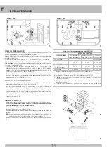
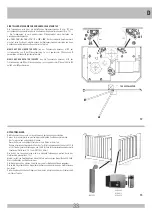
SAFETY CLUTCH ADJUSTMENT

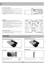
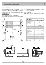
Lift the cover of the box to reveal the adjuster screw of the mechanical clutch located on 
top of the speed reducer casing (Fig. 14).
Remove the black protective cap, release the lock nut, and rotate the screw clockwise to 
increase the force transmitted by the motor to the gate.
The adjustment should be made in such a way as to obtain a force marginally greater than 
that effectively required to set the gate in motion.

N.B.:  More force you set on the motor clutch, less reversibility you obtain from the 

operator.

MAINTENANCE

To be undertaken by specialized staff after disconnecting power supply.

-  Make certain that moving parts located inside the box are greased once a year, and check 

the force transmitted through the drive to the gate.

-  The motor should be overhauled every two years and the oil replaced. In the event that 

the need for servicing or repairs should arise, the speed reducer can be removed from 
the box without taking down the gate.

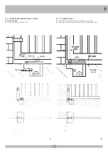
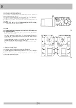
-  Lift the cover from the box, isolate the motor from the power supply by disconnecting the 

cable, then remove the curved lever: the gate can now swing freely.

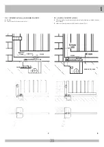
-  Thereafter, loosen the four nuts which secaure the fixing plate to the box and serve to 

clamp the speed reducer in position (Fig.15-A/B).

ELECTRICAL SAFETY DEVICES

 The installation must be installed according to the current regulations and laws. Use the T2 
(for one or two single-phase motors) electronic control unit. For connections and technical 
data of accessories refer to the appropriate booklets.

14

15

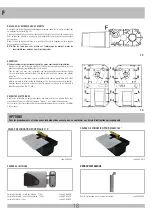
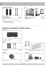
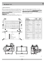
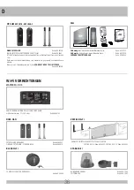
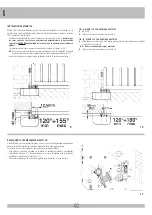
MECHANICAL BOLT

For 2-leaf gates to latch closed gate to the ground. 

code ACG5000

ACCESSORIES

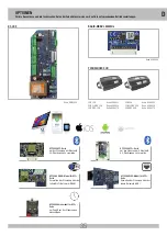
 For the connections and the technical data of the optional equipments follow the relevant handbooks.

G

B

FOUNDATION BOX FOR MAGIC 110°

code ACG8402

FOUNDATION BOX FOR MAGIC 180°

code ACG8412

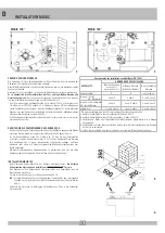
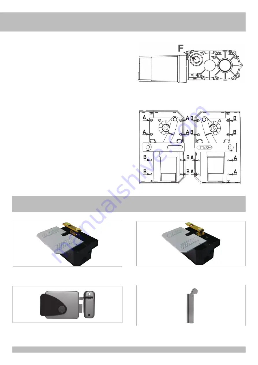
ELECTRIC LOCK

Horizontal lock - right external view - 12Vac 

code ACG8660

Horizontal lock - left external view - 12Vac 

code ACG8670

Vertical lock - 12Vac 

code ACG8650

Summary of Contents for AA10920M

Page 1: ...0932M ACG8412 Vedere pagina 11 Voir page 19 See page 27 Siehe Seite 35 Ver página 43 Il corretto funzionamento dell operatore è garantito solo se viene gestito da un quadro di comando RIB Le bon fonctionnement de l opérateur n est garanti que s il est géré par un panneau de contrôle RIB The correct operation of the operator is guaranteed only if it is managed by a RIB control panel Die korrekte Be...

Page 2: ...osservanza nell installazione delle norme di sicurezza e delle leggi attualmente in vigore ATTENTION POUR LA SECURITE DES PERSONNES IL EST IMPORTANT DE SUIVRE TOUTES LES INSTRUCTIONS CONSERVER SOIGNEUSEMENT CES INSTRUCTIONS 1 Si ce n est pas prévu dans la centrale installer en amont de celle ci un interrupteur de type magnétothermique omnipolaire avec ouverture minimum des contacts de 3 mm qui por...

Page 3: ...the non observance during the installation of the safety standards and of the laws in force at present ACHTUNG FÜR DIE SICHERHEIT DER PERSONEN IST ES WICHTIG DASS ALLE ANWEISUNGEN GENAU AUSGEFÜHRT WERDEN INSTALLATIONSVORSCHRIFTEN BEACHTET WERDEN 1 Wenn nicht bereits an der elektrischen Schaltzentrale vorgesehen muss vor der Schaltzentrale ein thermomagnetischer Schalter installiert werden omnipola...

Page 4: ...cquisto di una nuova apparecchiatura di tipo equivalente Presso i distributori di prodotti elettronici con superficie di vendita di almeno 400 m2 è inoltre possibile consegnare gratuitamente senza obbligo di acquisto i prodotti elettronici da smaltire con dimensioni inferiori a 25 cm L adeguata raccolta differenziata per l avvio successivo dell apparecchiatura dismessa al riciclaggio al trattament...

Page 5: ...ne di velocità dell anta sia in apertura che in chiusura apertura iniziale lenta poi veloce e chiusura inizialmente veloce poi lenta all arrivo in battuta MAGIC nella versione 180 Fig 4 permette l apertura dell anta fino a 180 se l albero di uscita del motore è in asse coi cardini dell anta Se l albero di uscita del motore è sfalsato dai cardini fino a 4 5 cm allora permette l apertura dell anta f...

Page 6: ...amente collocata da terra ad un altezza minima di sicurezza Con una livella posizionare la cassa in modo che il filo superiore del coperchio corrisponda al piano finito del pavimento CEMENTAZIONE DEL MAGIC 105 Cementare facendo attenzione che la malta non entri all interno della cassa e verificando che i lati più corti della cassa siano perfettamente paralleli al cancello quando è in posizione CHI...

Page 7: ...mm A NON USARE B Saldare al cancello con il perno come da Fig 7 FIG 8 LEVA DI TRAINO PORTANTE DEL CANCELLO A Usare solo quando il peso del cancello grava sul motore B Saldare con il perno a metà asola della leva di traino come da Fig 8 7 8 SCARICO ACQUA SALDARE CAVI ELETTRICI SALDARE ...

Page 8: ...5 tranne che per quanto segue Cementare facendo attenzione che la malta non entri all interno della cassa verificando che i lati più corti del cassonetto siano perfettamente perpendicolari al cancello quando è in posizione CHIUSO a seconda dell angolo d apertura che si vuole realizzare Il collegamento tra anta e leva di traino può avvenire come da figure 9 e 10 N B In caso l anta abbia un supporto...

Page 9: ...GENZA Da effettuare dopo aver tolto l alimentazione elettrica al motore Per poter eseguire in modo sicuro la movimentazione manuale dell anta occorre verificare che Siano fornite idonee maniglie sull anta Tali maniglie non siano posizionate in modo da creare punti di pericolo durante il loro utilizzo Lo sforzo manuale per muovere l anta non deve superare i 225 N per i cancelli posti su siti privat...

Page 10: ...bile rimuoverlo dalla cassa senza togliere l anta Dopo aver rimosso il coperchio del cassonetto e aver scollegato il cavo di alimentazione del motore estraete manualmente la leva curva di traino così da poter aprire l anta Di seguito svitate i quattro dadi che fissano la piastra alla cassa e che bloccano il riduttore in posizione Fig 15 A B SICUREZZE ELETTRICHE Realizzare l impianto in ottemperanz...

Page 11: ...Orologio per Scheda APP con Modulo Wi Fi o RJ45 per gestire la centrale di comando come controllo accessi APP8050 Scheda APP per gestire la centrale di comando tramite Bluetooth APP8054 Scheda APP per gestire la centrale di comando tramite Bluetooth APP8064 Modulo Wi Fi per Scheda APP per gestire la centrale tramite rete Wi Fi locale WLAN APP8066 Modulo RJ45 per Scheda APP per gestire la centrale ...

Page 12: ...NZA FILI NOVA Wi Fi FOTOCELLULE SENZA FILI cod ACG8037 COPPIA COLONNINE NOVA cod ACG8039 VERTIGO Wi Fi FOTOCELLULE SENZA FILI SOSTITUTIVE DELLA COSTA VERTIGO Wi Fi 8 cod ACG8042 VERTIGO Wi Fi 10 cod ACG8043 BLOCK Wi Fi SELETTORE A CHIAVE SENZA FILI cod ACG6098 SPARK Wi Fi LAMPEGGIATORE SENZA FILI cod ACG7064 SUPPORTO LATERALE cod ACG7042 I SAIL SAIL arancio con scheda intermittente incorporata cod...

Page 13: ...ermeture ouverture lente au début puis rapide fermeture rapide au début puis lente à l arrivé en butée MAGIC dans la version 180 Fig 4 permet l ouverture du vantail jusqu à 180 si l arbre en sortie de moteur se trouve dans l axe des gonds du vantail Si l arbre en sortie de moteur se trouve décalé de 4 5 cm alors permet l ouverture du vantail jusqu à 150 Mesures en mm 2 1 50 416 107 58 Ø35 Ø65 261 ...

Page 14: ...à une hauteur minimale de sécurité et devra répondre aux normes A l aide d un niveau positionner le caisson de façon à ce que le bord supérieur du couvercle soit au ras du sol C IMENTER LE MAGIC 105 Cimenter en faisant attention à ce que le mortier ne pénètre pas à l intérieur du caisson et en s assurant que les côtés les plus courts du caisson sont parfaitement parallèles au portail lorsque celui...

Page 15: ...B Souder au portail avec le pivot cf fig 7 FIG 8 PORTANT DU PORTAIL A Utiliser uniquement lorsque le poids du portail repose sur le moteur B Souder avec le pivot au milieu de la fente du levier d entraînement cf fig 8 7 8 ECOULEMENT DE L EAU SOUDER CABLE ELECTRIQUE SOUDER ...

Page 16: ... du 105 sont valables De plus Cimenter en prenant soin de ne pas introduire de mortier dans le caisson en veillant à ce que les côtés les plus courts du caisson soient parfaitement perpendiculaires au portail en position FERME selon l angle d ouverture que l on désire obtenir Le raccordement entre vantail et fourche peut être fait comme indiqué figures 9 10 N B Lorsque le portail déjà installé dis...

Page 17: ...upé l alimentation Afin de pouvoir manœuvre manuellement le vantail il est important de vérifier que Il soit fourni des poignées adaptées sur le vantail Ces poignées doivent être positionnées de sorte à ne pas créer un danger durant leur utilisation L effort manuel pour mettre en mouvement le vantail ne doit pas excéder 225 N pour les portes et portails en usage privé et 390 N pour les portes et p...

Page 18: ...éducteur il est possible de le sortir du caisson sans enlever le vantail Après avoir ôté le couvercle du caisson et débranché le câble d alimentation du moteur extraire à la main le levier courbe de déplacement de façon à pouvoir ouvrir le vantail Dévisser ensuite les quatre écrous qui fixent la plaque au caisson et qui bloquent le réducteur en position Fig 15 A B SECURITES ELECTRIQUES Adapter les...

Page 19: ...etooth 4 2 APP8064 Module Wi Fi pour Carte APP pour gérer le tableau de contrôle via un réseau Wi Fi local WLAN APP8066 Module RJ45 pour Carte APP pour gérer le tableau de contrôle via un réseau de données local LAN MODULE RADIO 433MHz code ACG8069 EMETTEUR RADIO SUN SUN 2CH code ACG6052 SUN 4CH code ACG6054 SUN CLONE 2CH code ACG6056 SUN CLONE 4CH code ACG6058 SUN PRO 2CH code ACG6210 SUN PRO 4CH...

Page 20: ...E ET SECURITE SANS FILS NOVA Wi Fi PHOTOCELLULES SANS FILS code ACG8037 PAIRE DE POTEAUX NOVA code ACG8039 VERTIGO Wi Fi PHOTOCELLULES SANS FIL POUR REMPLACER LA BARRE PALPEUSE VERTIGO Wi Fi 8 code ACG8042 VERTIGO Wi Fi 10 code ACG8043 BLOCK Wi Fi SÉLECTEUR À CLÉ SANS FILS code ACG6098 SPARK Wi Fi FEU CLIGNOTANT SANS FILS code ACG7064 SUPPORT LATERAL code ACG7042 F MASTER Wi Fi OS FICHE DE GESTION...

Page 21: ... the opening and closing movements opening movement initially slow then fast closing movement initially fast then slow immediately before shutting MAGIC 180 version fig 4 installing this version a gate can be rotated through 180 if the drive shaft is coaxially aligned with the hinge centre or through 150 with the drive shaft offset from the centre of rotation by up to 4 5 cm Measurements in mm 2 1...

Page 22: ...nsure compliance with safety standards Position the foundation box in the pit so that the topmost surface of the cover is flush with the finished floor or paving MAGIC 105 INSTALLATION Anchor the box with cement mortar taking care that none of the mix finds its way into the enclosure and checking that the shorter sides are faultlessly parallel with the gate when in the SHUT position Couple the tra...

Page 23: ... Weld to the gate with the pivot as shown in Fig 7 FIG 8 TRANSMISSION LEVER GATE LOAD BEARING SUPPORT A Use only when the gate weighs excessively on the motor B Weld with the pivot inserted half way into the transmission lever slot as shown in Fig 8 7 8 WATER DRAIN WELD POWER CABLE WELD ...

Page 24: ...e following exception Anchor the box with cement mortar taking care that none of the mix finds its way into the enclosure and checking that the shorter sides are faultlessly square with the gate when in the SHUT position depending on the required opening arc The connection between gate and lever can be made as indicated in figs 9 and 10 NB When converting an existing gate with a load bearing suppo...

Page 25: ...A1 or B1 according to the opening arc required EMERGENCY RELEASE To be undertaken after disconnecting power supply In order to carry out the manual operation of the gate leaf the followings must be checked That the gate is endowed with appropriate handles That these appropriate handles are placed so to avoid safety risks for the operator That the physical effort necessary to move the gate leaf sho...

Page 26: ...hould arise the speed reducer can be removed from the box without taking down the gate Lift the cover from the box isolate the motor from the power supply by disconnecting the cable then remove the curved lever the gate can now swing freely Thereafter loosen the four nuts which secaure the fixing plate to the box and serve to clamp the speed reducer in position Fig 15 A B ELECTRICAL SAFETY DEVICES...

Page 27: ...access control features to the control panel APP8064 Wi Fi module for APP card to manage the control panel using the local Wi Fi network WLAN APP8066 RJ45 module for APP card to manage the control panel using the local network LAN RADIO MODULE 433MHz code ACG8069 RADIO TRANSMITTER SUN SUN 2CH cod ACG6052 SUN 4CH cod ACG6054 SUN CLONE 2CH cod ACG6056 SUN CLONE 4CH cod ACG6058 SUN PRO 2CH cod ACG621...

Page 28: ... Fi PHOTOCELLS WITHOUT WIRES code ACG8037 PAIR OF COLUMS NOVA code ACG8039 VERTIGO Wi Fi WIRELESS PHOTOCELLS SUBSTITUTING THE SAFETY STRIP VERTIGO Wi Fi 8 code ACG8042 VERTIGO Wi Fi 10 code ACG8043 BLOCK Wi Fi KEY SELECTOR WITHOUT WIRES code ACG6098 SPARK Wi Fi BLINKER WITHOUT WIRES code ACG7064 LATERAL SUPPORT code ACG7042 G B SAIL SAIL orange with built in flashing board code ACG7072 SAIL white ...

Page 29: ... 105 Abb 3 ein Flügel Verzögerungssystem sowohl bei der Öffnungs als auch bei der Schließbewegung Beschleunigung der anfänglich langsamen Öffnungsbewegung und Verzögerung der Schließbewegung am Anschlag auf MAGIC Version 180 Abb 4 Bei koaxialer Position von Motorabtriebswelle und Flügelscharnieren beträgt die max Flügelöffnung 180 150 dagegen bei versetztem Einbau bis zu 4 5 cm von Welle und Schar...

Page 30: ...bstand vom Boden befestigen Mit einer Wasserwaage das Getriebegehäuse so positionieren daß sich die obere Abdeckungskante höhengleich mit dem fertigen Boden zu liegen kommt INSTALLATION MAGIC 105 Beim Einmauern keinen Zement in das Gehäuse eindringen lassen Die kürzeren Gehäuseseiten müssen genau parallel zum GESCHLOSSENEN Tor sein Den Zughebel auf die Gehäusewelle Schmieren setzen und sicherstell...

Page 31: ...A NICHT VERWENDEN B Mit dem Stift an das Tor schweißen vgl Abb 7 ABB 8 ZUGHEBEL TRÄGT DAS TORGEWICHT A Nur verwenden wenn das Torgewicht auf dem Motor lastet B Mit dem Stift in der Mitte des Zughebels schweißen vgl Abb 8 7 8 WASSERABFLUSS SCHWEISSEN ELEKTROKABEL SCHWEISSEN ...

Page 32: ...nkten wird diese Version entsprechend Version 105 installiert Beim Einmauern keinen Zement in das Gehäuse eindringen lassen Die kürzeren Gehäuseseiten müssen genau senkrecht zum GESCHLOSSENEN Tor sein Für den Anschluß zwischen Tor und Zughebel siehe Abb 9 10 N B Für bereits bestehende Tore mit bodenseitiger Trägerstruktur kann die tragende Funktion bei der Installation vom Motor übernommen werden ...

Page 33: ...onieren NOTENTRIEGELUNG Die Wartungsarbeit nur nach der Ausschliessung der Spannung auszuführen Um das Tor manuell richtig zu pruefen muessen folgende Punkte beachtet werden Das Tor muss einen geeigneten Griff haben Dieser Griff muss so angebracht sein das er kein Risiko ist beim Test Daß die physische notwendige Kraft um das Tor Blatt zu bewegen nicht höher als 225 N ist für Tore bei privaten Woh...

Page 34: ...ie Bewegungsteile im Getriebekasten jährlich schmieren und die Druckkraft des Getriebes auf das Tor überprüfen Alle 2 Jahre Überholung durchführen und ggf Öl und Keilriemenwechsel vornehmen Das Getriebe kann für Wartungsarbeiten aus dem Gehäuse entfernt werden ohne den Torflügel zu demontieren Die Gehäuseabdeckung abnehmen die Stromzufuhr zum Motor unterbrechen den Bewegungshebel von Hand herauszi...

Page 35: ...4 2 Übertragung zu verwalten APP8060 Uhrenmodul für APP Karte um Zugriff auf das Steuerungen hinzuzufügen APP8064 WLAN Modul für APP Karte Verwalten des Steuerung über das lokale Wi Fi Netzwerk WLAN APP8066 RJ45 Modul für APP Karte Verwalten der Steuerung über das lokale Netzwerk LAN RADIO MODUL 433MHz Kode ACG8069 FERNSENDER SUN SUN 2CH Kode ACG6052 SUN 4CH Kode ACG6054 SUN CLONE 2CH Kode ACG6056...

Page 36: ...LEN OHNE KABEL Kode ACG8037 EIN PAAR FOTOZELLEN STÄNDER NOVA Kode ACG8039 VERTIGO Wi Fi KABELLOSE FOTOZELLE ERSETZT DIE SCHALTLEISTEN VERTIGO Wi Fi 8 Kode ACG8042 VERTIGO Wi Fi 10 Kode ACG8043 BLOCK Wi Fi SCHLÜSSELSCHALTER OHNE KABEL Kode ACG6098 SPARK Wi Fi BLINKER OHNE KABEL Kode ACG7064 SEITENLAGER Kode ACG7042 D MASTER Wi Fi OS KARTE FÜR DEN BETRIEB DES SYSTEMS OHNE KABEL mit Endblockierung 12...

Page 37: ...n la version 105 fig 3 está dotado de variacion de velocidad de la hoja ambos durante la abertura y el cierre comienzo de la abertura lento después rápido y al fin cerra lento cuando la hoja acerca el tope MAGIC en la version 180 fig 4 permite la abertura de la hoja hasta 180 si el eje del motor y las bisagras de la hoja son coincidentes Si estan distanciados hasta 4 5 cm 150 Mesures en mm 2 1 50 ...

Page 38: ... La caja de ensambladura puede ser empotrada o fixada sobre la superficie colocada en una altura segura y debe conformarse con la normas Con un nivel posicionar la caja de modo que el borde superior de la tapa corresponde al plano acabado del suelo INSTALACIÓN DE MAGIC 105 Cementar prestando atención que el cemento no caiga dentro la caja y controlar que las caras cortas de la caja estén perfectam...

Page 39: ...n el perno como en Fig 7 FIG 8 MAGIC 105 PORTANTE DE LA PUERTA A Utilice solo cuando el peso de la puerta grava sobre el motor y tiene que ser soldado a la puerta con un refuerzo B Soldar con el perno posicionado a mitad ranura de la palanca Fig 8 7 8 DRENAJE DEL AGUA SOLDAR CABLES ELÉCTRICOS SOLDAR ...

Page 40: ...a versión 105 a excepción del siguiente Cementar prestando atención que el cemento no caiga dentro la caja y controlar que las caras cortas de la caja sean perfectamente perpendicular a la hoja cuando en posición CERRADO dependiendo de la anchura de la abertura que usted desea obtener La conexión entre la hoja y la palanca se puede hacer según las figuras 9 y 10 NB En caso de puertas existentes co...

Page 41: ...òn al motor Para poder realizar en modo seguro el desplazamiento manual de la puerta hay que controlar que Las manillas de la puerta que se han proporcionado sean idóneas Estas manillas no estén posicionadas en modo de crear puntos de peligro durante su utilizo El esfuerzo manual para mover la puerta no debe superar los 225 N para las cancelas colocadas en lugares privados y los 390 N para las can...

Page 42: ...especializado y con el motor desconectado de la alimentación eléctrica Cada año poner grasa sobre las piezas que se mueven dentro de la caja y controlar la fuerza ejercitada por el motor sobre la puerta Cada dos años es mejor una manutención al reductor substituyendo aceite En caso que se necesite hacer manutención al reductor es posible quitarlo de la caja sin desmontar la hoja Despues de haber q...

Page 43: ...54 Tarjeta APP para administrar la unidad de control a través de Bluetooth 4 2 APP8064 Módulo wi fi para Tarjeta APP para administrar el panel de control a través de una red Wi Fi local WLAN APP8066 Módulo RJ45 para Tarjeta APP para administrar el panel de control a través de una red local LAN MÓDULO RADIO 433MHz cod ACG8069 TELEMANDO SUN SUN 2CH cód ACG6052 SUN 4CH cód ACG6054 SUN CLONE 2CH cód A...

Page 44: ...SPOSITIVOS Wi Fi NOVA Wi Fi FOTOCÉLULAS SIN CABLES cód ACG8037 PAR DE COLUMNAS NOVA cód ACG8039 VERTIGO Wi Fi FOTOCÉLULAS SIN CABLES PARA REEMPLAZAR A LA COSTA VERTIGO Wi Fi 8 cód ACG8042 VERTIGO Wi Fi 10 cód ACG8043 BLOCK Wi Fi SELECTOR DE LLAVE SIN CABLES cód ACG6098 SPARK Wi Fi INTERMITENTE SIN CABLES cód ACG7064 SOPORTE LATERAL cód ACG7042 E S SAIL SAIL naranja con tablero intermitente incorpo...

Page 45: ...45 ...

Page 46: ...2 Pignone CME6983 Leva di traino MAGIC 105 CME6985 Leva di traino MAGIC 180 CME8002 Puntale per frizione CME8003 Disco frizione CME9276 Flangia anteriore CME9809 Leva CME9810 Leva traino CME9814 Perno traino CME9815 Semi carcassina DX CME9817 Albero di traino CME9820 Pignone traino MAGIC 180 CME9822 Ingranaggio ballerino Z 27 CME9823 Blocchetto fermo Magic 180 CME9825 Semi carcassina SX CME9826 Co...

Page 47: ...6092 Corona Z 39 CME6093 2 Pignone CME6983 Leva di traino MAGIC 105 CME6985 Leva di traino MAGIC 180 CME8002 Puntale per frizione CME8003 Disco frizione CME9276 Flangia anteriore CME9809 Leva CME9810 Leva traino CME9814 Perno traino CME9815 Semi carcassina DX CME9817 Albero di traino CME9820 Pignone traino MAGIC 180 CME9822 Ingranaggio ballerino Z 27 CME9823 Blocchetto fermo Magic 180 CME9825 Semi...

Page 48: ...ß Anhang I der Richtlinie UE 2006 42 CE angewendet wurden Die Übereinstimmung mit den genannten harmonisierten Normen sieht die Vermutung der Übereinstimmung mit den festgelegten grundlegenden Anforderungen der Richtlinie vor die unter diese Normen oder Teile davon fallen ACHTUNG Weitere Anforderungen und andere EU Richtlinien können für Produkte dieser Erklärung unterliegen angewendet werden Los ...

Reviews: