

9
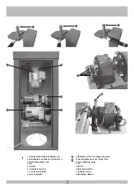
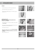
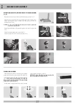
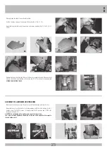
MONTAGGIO MOZZI PER ASTE IN ALLUMINIO
-
Portare manualmente l’asta in posizione orizzontale.
-
Tirare con chiave a brugola n° 5 le 2 viti di tenuta asta (Fig. 31-32).
-
Montare la protezione utilizzando le rondelle e viti in dotazione (Fig. 33-34-35-36-37-
38-39).
-
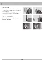
Rilasciare l’asta verificando che si alzi fino al raggiungimento della completa apertura.
In caso l’asta non si alzi, verificare il corretto tiraggio della molla (Fig. 40-41) come
riportato nell’apposita
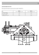
TABELLA TARATURA MOLLE
.
44
31
43
42
33
37
35
39
46
32
34
38
36
47
45
-
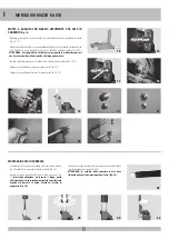
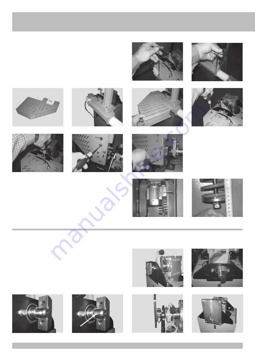
Prendere la linguetta ad incastro 8x7x20 ed inserirla nella sede dell’albero porta mozzo
(Fig. 44-45).
-
Montare il mozzo sull’albero in corrispondenza dello spacco con linguetta bloccandolo con
2 viti TCEI 10x70 inox, 4 rondelle 10x20 inox e 2 dadi M10 autobloccanti (Fig. 46-47).
ATTENZIONE: Non serrare a fondo solo una delle due viti.
Il serraggio delle viti deve essere eseguito in modo alternato così che il mozzo
risulti fissato parallelo rispetto all’albero porta mozzo.
41
40
I


