background image

35

(always use the right tool to ensure compliance with the values imposed by the standard), 

without special adjustments on the control panel, as it operates using special internal 

software. If the power sensor is used in opening or closing (only in high-speed) and then 

again, in the opposite direction, the gate stops and then reverses for 1 second. 

The alarm status will be displayed by the blinker which will remain active for one minute, 

during which time you can restore gate operation by pressing any command button.

FUNCTIONING IN DEAD MAN MODE WHEN THE SAFETY DEVICES ARE FAILING

If the safety edge fails or remains engaged for more than 5 seconds, or if photocell fails 

or remain engaded for more than 60 seconds,  the open, close, k button and pedestrian 

commands will work only in dead man mode.

The signal that this mode has been activated is given by the blinking of the programming led.

With the blinking of the programming led, the opening and closing operation are allowed 

only with the command button pressed and held. The radio commands and that of automatic 

closing, will be excluded, since their use in this mode, is not allowed by the norms.

Once the failing safety device is repaired,  in automatic after 1 second, all standard 

commands that were selected, such as step by step, automatic mode, radio commands and 

automatic closing start functioning again.

Note 1:

  during this functioning in dead man mode, in case of damage to the safety strips 

(or photocells) the photocells (or safety strips) still work by interrupting the operation 

in progress.

Note 2:

  the stop command is not to be considered a safety command that can be bypassed 

in this mode. Therefore, when pressed or damaged, it will not allow any movement 

of the gate.

The dead-man operation is only an emergency operation which must be activated for 

a very short period and with the complete installation at sight so to have a secure and 

safe control of the system. As soon as possible however, the failing safety devices 

must be repaired and activated.

BLINKER

N.B.:

 This control panel can power ONLY BLINKERS ON A (ACG7061) CIRCUIT with lamps 

up to 24V and 20W.

PRE-BLINKING

DIP 5 - OFF => the motor and blinker begin simultaneously.

DIP 5 - ON => the blinker begins 3 seconds before the motor.

GATE OPEN WARNING LIGHT (COM-SIGNAL)

Signals when the gate is open, partially open or not closed completely. Turns off only when 

the gate is completely closed. This signal is active during programming. 

N.B.: 

Max 3 W. If 

push buttons or lamps are in excess, the control panel processes will be endangered and 

possibly halt operation.


OPERATION AFTER A BLACK-OUT (WITHOUT BATTERIES)

When the power supply comes back the DL1 led turns on and remains on for all the time 

the gate stays open. The led will turn off only once the gate is completely closed. It is 

recommended to fully open the gate. Let the gate close by itself or with automatic closing, or 

wait until the blinker stops flashing before commanding it to close.

This will allow the gate to realign. If, motors were released and moved from the normal 

position when closed during the blackout, the first movement after power returns must be 

complete.

If the black out occurs when the gate is still moving or when the gate is open and the first 

command sent after the black out is a closing command, the closing of the gate will be 

carried out with a total delay between the two gate leaves. Therefore, first the leaf M2 will 

close completely; once it is off, M1 will start closing. This separate movement of the two gate 

leaves is done to avoid their incorrect overlapping.

TECHNICAL SPECIFICATIONS

- Temperature range 

0 ÷ 55°C

- Humidity 

 <95% without condensation

- Voltage 

230V~ ± 10%   (120V/60Hz upon request)

- Frequency 

50/60 Hz

- Battery power 

20-24Vdc

- Transformer Power 

 130VA - primary 230Vac - secondary 18Vac

- Maximum absorption 

50 mA

- Network Micro-switches 

100ms

- Maximum power gate open indicator   24Vdc 3W (equivalent to one 3W or 5 LED light 

bulb with resistor in series at 2.2 K ohm)

- Maximum blinker power 

24Vdc 20W

- Power available for photocells and accessories  1A ± 15%

- Power available for radio connector  200mA

RADIO SPECIFICATIONS (model T2 24V CRX)

- Receiving Frequency 

433,92 MHz

- Impedance 

52 OHM

- Sensitivity 

>2,24µV

- Pick-up time 

300ms

- Drop time 

300ms

-  All inputs must be used as clean contacts because the power is generated internally (secure 

power) to the board and is set up to ensure compliance with double or reinforced insulation 

with regard to dangerous voltage.

-  Any external circuits connected to the outputs of the control panel must be made in such 

a manner as to ensure compliance with double or reinforced insulation with regard to 

dangerous voltage.

-  All inputs are controlled by a programmed integrated circuit that performs a self check every 

time it starts operating.

TROUBLE SHOOTING

After having carried out all connections, by carefully following the layout and having positioned 

the gate in intermediate position, check the correct ignition of red LEDS DL7, DL8 and DL9

In case of no ignition of the LEDS, always with gate in intermediate position, check the 

following and replace any faulty components.

DL7  switched  OFF  Faulty photocells

DL8 switched  OFF  

Faulty safety edge (In case the edge is not connected, carry out 

jumper between COM and EDGE)

DL9 switched  OFF  

Stop button malfunction (if Stop is not connected, perform the jump 

between COM and STOP).

During functioning with personnel present, with DIP 1 at ON, check that during opening of 

M1 and M2 the green DL2 and DL4 LEDS switch on and that during closing of M1 and M2 

the red DL3 and DL5 LEDS switch on.

Or else, reverse the wires of the motor.

G

B

FAULT

SOLUTION

After having carried out the various connections and having supplied 
voltage, all the LEDS are switched off.

Check fuses F1, FUSE 1. 
If the fuse is blown, use only a suitable replacement.
F1 T 2A 

 TRANSFORMER PROTECTION FUSE (on the outside of the T2 24V board)

FUSE 1 8A  MOTOR PROTECTION FUSE

The motor opens and closes, but it has no strength and moves slowly.

Check trimmers RUN and LOW-SPEED adjustment.

The gate opens but does not close after the time set.

Make sure that the TCA trimmer is activated with LED DL6 on. 
OPEN button always on, replace the OPEN control button or switch. 
Sensor Auto test failed, check the connections between the control panel and the sensor power supply. 

Warning:

 If you are not using a power supply for the sensors, DIP 12 should be OFF.

The gate does not open or close by activating the various K, Radio, Open 
and Close buttons.

Faulty safety edge contact. Faulty photocells contact with DIP 4 OFF.
Fix or replace the relative contact.

The electric lock does not work.

Ensure to have enabled DIP 8 at ON.

LED DL1 blinks rapidly and no movement is activated.

Place dip switches 1, 2 or 3 in the OFF position.

Summary of Contents for AD00732

Page 1: ...ateur Operator Torantrieb Operador Alimentazione Alimentation Power Supply Stromspannung Alimentacion Peso max anta Poids maxi battant Max leaf weight Max Torgewicht Peso max hoja Spinta Poussée Thrust Schubkraft Empuje Spinta max Poussée maxi Max thrust Max Schubkraft Empuje max Codice Code Code Code Codigo KIT PRINCE 24V 230V 50 60Hz 250 kg 550 lbs 100 kg 220 lbs 140 kg 309 lbs AD00732 KIT PRINC...

Page 2: ...nell installazione delle norme di sicurezza e delle leggi attualmente in vigore ATTENTION POUR LA SECURITE DES PERSONNES IL EST IMPORTANT DE SUIVRE TOUTES LES INSTRUCTIONS CONSERVER SOIGNEUSEMENT CES INSTRUCTIONS 1 Si ce n est pas prévu dans la centrale installer en amont de celle ci un interrupteur de type magnétothermique omnipolaire avec ouverture minimum des contacts de 3 mm qui porte une marq...

Page 3: ...caused by the non observance during the installation of the safety standards and of the laws in force at present ACHTUNG FÜR DIE SICHERHEIT DER PERSONEN IST ES WICHTIG DASS ALLE ANWEISUNGEN GENAU AUSGEFÜHRT WERDEN INSTALLATIONSVORSCHRIFTEN BEACHTET WERDEN 1 Wenn nicht bereits an der elektrischen Schaltzentrale vorgesehen muss vor der Schaltzentrale ein thermomagnetischer Schalter installiert werde...

Page 4: ...normas EN 12453 EN 12445 4 El instalador antes de instalar el motor de desplazamiento tiene que controlar que la cancela esté en buenas condiciones mecánicas y que se abra y se cierre en forma adecuada 5 El instalador tendrá que instalar el órgano para el desenganche manual a una altura inferior a 1 8 m 6 El instalador tendrá que quitar eventuales impedimentos para el movimiento motorizado de la c...

Page 5: ...lizza anche il fermo meccanico che interviene durante la chiusura opzionale la corsa massima di traino si riduce di 30 mm 1 5 5 4 4 3 2 1 LAYOUT IMPIANTO I CARATTERISTICHE TECNICHE PRINCE 24V Lunghezza max anta m 3 Peso max anta kg 250 Corsa max di traino mm 343 Tempo medio di apertura s 17 Velocità media di traino m s 0 0134 Alimentazione 24Vdc Potenza nominale a 71 rpm vite W 12 Potenza a blocco...

Page 6: ...ella norma EN12453 Appendice A E Fotocellule es cod ACG8026 Da applicare ogni 60 70cm per tutta l altezza della colonna del cancello fino ad un massimo di 2 5m EN 12445 punto 7 3 2 1 SBLOCCO DI EMERGENZA In caso di mancanza di corrente per poter agire manualmente sul cancello è sufficiente inserire l apposita chiave e ruotarla di 90 in senso antiorario Fig 3 Per poter eseguire in modo sicuro la mo...

Page 7: ... 100 100 765 90 13 5 S3 X A 60 110 100 765 90 14 S3 Y A 80 140 110 765 115 17 S3 X B 100 160 110 765 115 18 S3 X B 120 180 110 765 115 19 5 S3 X B 140 210 110 765 115 21 5 S1 Z B 150 220 120 765 115 23 S1 Z B 20 110 140 765 90 17 S1 Y A Misure da rispettare CON 2 FERMI MECCANICI 110 90 L Min Max a A max T sec B C D E 1 3 COL ANT 0 100 100 730 90 13 5 S2 X A 20 100 100 730 90 13 5 S2 X A 40 100 100...

Page 8: ...occarlo serrando la vite da 8mA con una chiave fissa n 13 Per ottenere la chiusura desiderata si dovrà spostare il fermo B OPZIONALE bloccandolo come descritto per il fermo A MANUTENZIONE Da effettuare solamente da parte di personale specializzato dopo aver tolto l alimentazione elettrica Ogni anno ingrassare i cardini e controllare la forza di spinta esercitata dall operatore sull anta Ogni due a...

Page 9: ...ZA ANTENNA CHIUDE APRE STOP FUSE T 2 A FOTOCELLULE PASSO PASSO COMUNE COMUNE 24Vdc 0 8A 15 per ACCESSORI 24Vdc 0 8A 15 per AUTOTEST COSTE LAMPEGGIATORE 24Vdc 20W LED R 2 2K 1 4W SERRATURA ELETTRICA PEDONALE COSTE ALIMENTAZIONE 230Vac 50Hz TRASFORMATORE M1 M2 ...

Page 10: ...RE DALLA EN12453 IN CASO NON SUSSISTA LA NECESSITA DI OTTEMPERARE ALLA NORMA SOPRA DESCRITTA E SUFFICIENTE POSIZIONARE IL DIP 3 IN OFF IN QUESTO CASO LE ANTE SI FERMERANNO SENZA INVERTIRE IL MOVIMENTO I A CONNESSIONI J3 TR2 TR1 J2 J4 F1 FUSE 1 J5 J6 TR3 J10 J8 J9 J1 J7 S3 TRANSFORMER J1 N F Alimentazione 230 Vac 50 60 Hz esterna alla scheda 120V 60Hz a richiesta J2 COM Comune dei contatti CLOSE Co...

Page 11: ...no il cancello 10 A FINE PROGRAMMAZIONE RIMETTERE IL DIP 2 SU OFF D PROGRAMMAZIONE TEMPI PER 1 MOTORE M1 CON SENSORE DI CORRENTE ABILITATO DIP 7 ON ATTENZIONE PER GESTIRE UN SOLO MOTORE IL DIP 13 DEVE ESSERE POSIZIONATO IN ON DURANTE LA PROGRAMMAZIONE IL SENSORE DI CORRENTE È SEMPRE ATTIVO Il cancello deve essere completamente chiuso 1 Mettete DIP 2 su ON Il led DL1 emetterà dei lampeggi brevi 2 P...

Page 12: ...ANDO SOLO SE IMPULSIVI Assicurarsi che eventuali altri tipi di accessori di comando per esempio sensori magnetici siano programmati nella modalità IMPULSIVA altrimenti attiverebbero la movimentazione del cancello senza sicurezze attive PULSANTE DI COMANDO PASSO PASSO COM K BUTTON Se DIP 6 su OFF Esegue un comando ciclico dei comandi apre stop chiude stop apre ecc Se DIP 6 su ON Esegue l apertura a...

Page 13: ...amento del cancello premendo un qualsiasi pulsante di comando FUNZIONAMENTO AD UOMO PRESENTE IN CASO DI GUASTO DELLE SICUREZZE Se la costa è guasta o impegnata per più di 5 secondi o se la fotocellula è guasta o impegnata per più di 60 secondi i comandi APRE CHIUDE K BUTTON E PEDONALE funzioneranno solo ad uomo presente La segnalazione dell attivazione di questo funzionamento è data dal led di pro...

Page 14: ...i DL2 e DL4 e che durante la chiusura di M1 e M2 si accendano i led rossi DL3 e DL5 In caso contrario invertire i fili del motore interessato I DIFETTO SOLUZIONE Dopo aver effettuato i vari collegamenti e aver dato tensione tutti i led sono spenti Verificare l integrità dei fusibili F1 FUSE 1 In caso di fusibile interrotto usarne solo di valore adeguato F1 T 2A FUSIBILE DI PROTEZIONE TRASFORMATORE...

Page 15: ...PPIA COLONNINE NOVA cod ACG8039 VERTIGO Wi Fi FOTOCELLULE SENZA FILI SOSTITUTIVE DELLA COSTA VERTIGO Wi Fi 8 cod ACG8042 VERTIGO Wi Fi 10 cod ACG8043 BLOCK Wi Fi SELETTORE A CHIAVE SENZA FILI cod ACG6098 MASTER Wi Fi SCHEDA DI GESTIONE SISTEMA SENZA FILI con innesto 12 30V ac dc cod ACG6094 con morsettiera 12 30V ac dc cod ACG6099 SPARK Wi Fi LAMPEGGIATORE SENZA FILI cod ACG7064 SUPPORTO LATERALE ...

Page 16: ...nt pendant l ouverture Si l on utilise aussi la butée mécanique qui intervient pendant la fermeture en option la course maximale d entraînement s écourte de 30 mm 1 5 5 4 4 2 CARACTERISTIQUES TECHNIQUES PREMIER 24V Longueur maxi du battant m 3 Poids maxi du battant kg 250 Course maxi d entrainement mm 343 Temps moyen d ouverture s 14 Vitesse de traction m s 0 0134 Alimentation et frequence 24Vdc P...

Page 17: ...me EN12453 appendice A E Cellules photo électriques code ACG8026 Appliquer chaque 60 70 cm pour toute la taille de la colonne de la porte jusqu à un maximum de 2 5 m EN 12445 point 7 3 2 1 MANOEUVRE DE SECOURS Pour actionner le portail manuellement il est necessaire introduire la clé appropriée dans la serrure et la tourner de 90 dans le sense anti horaire Fig 3 Afin de pouvoir manœuvre manuelleme...

Page 18: ...100 765 90 13 5 S3 X A 60 110 100 765 90 14 S3 Y A 80 140 110 765 115 17 S3 X B 100 160 110 765 115 18 S3 X B 120 180 110 765 115 19 5 S3 X B 140 210 110 765 115 21 5 S1 Z B 150 220 120 765 115 23 S1 Z B 20 110 140 765 90 17 S1 Y A Mesures de respecter AVEC DEUX ARRETS MECANIQUES 110 90 L Min Max a A max T sec B C D E 1 3 COL ANT 0 100 100 730 90 13 5 S2 X A 20 100 100 730 90 13 5 S2 X A 40 100 10...

Page 19: ...r le collier A et de le bloquer en vissant la vis M8 avec une clé n 13 Pour obtenir la fermeture desirée il est necessarie de deplacer le collier B OPTIONAL et de le bloquer comme indiqué ci dessus ENTRETIEN Effectuer seulement par personnel specialisé après avoir coupé l alimentation Tous les ans graisser les gonds et contrôler la force de poussée exercée par le motoréducteur sur le portail Tous ...

Page 20: ...ELLULES PAS A PAS COMMUN COMMUN 24Vdc 0 8A 15 pour ACCESSOIRES 24Vdc 0 8A 15 AUTOTEST pour BARRE PALPEUSE FEU CLIGNOTANT 24Vdc 20W LED R 2 2K 1 4W SERRURE ÉLECTRIQUE PIETON BARRE PALPEUSE ALIMENTATION 230Vac 50Hz TRANSFORMATEUR M1 M2 T2 24V code AC07088 T2 24V CRX code AC07089 ...

Page 21: ...SIBLES RESPECTANT AINSI LES TESTS D IMPACT INDIQUES EGALEMENT PAR LADITE NORME DANS LE CAS OU VOUS NE POURRIEZ PAS RESPECTER LES PRESCRIPTIONS DE LA NORME 12453 POSITIONNER LE DIP 3 SUR OFF DANS CE CAS LES PORTES S ARRETERONT SANS INVERSER LE MOUVEMENT A BRANCHEMENTS J3 TR2 TR1 J2 J4 F1 FUSE 1 J5 J6 TR3 J10 J8 J9 J1 J7 S3 TRANSFORMER J1 N F Alimentation 230Vac 50 60Hz externe à la fiche 120V 60Hz ...

Page 22: ...ent le portail 10 A LA FIN DE LA PROGRAMMATION REMETTRE LE DIP 2 SUR OFF D PROGRAMMATION DES TEMPS POUR 1 MOTEUR M1 AVEC CAPTEUR DE COURANT ACTIVE DIP 7 ON ATTENTION POUR NE GERER QU UN MOTEUR LE DIP 13 DOIT ETRE POSITIONNE SUR ON PENDANT LA PROGRAMMATION LE DETECTEUR DE COURANT EST TOUJOURS ACTIVE Le portail doit être totalement fermé 1 Mettez DIP 2 sur ON la DEL DL1 émettra des clignotements bre...

Page 23: ...tail est fermé S il est actionné pendant le mouvement d ouverture cela ne produit aucun effet S il est actionné lorsque le portail est ouvert il le ferme S il est actionné pendant la fermeture du portail il le rouvre POUSSOIR D OUVERTURE COM OPEN Lorsque le portail est fermé le poussoir commande le mouvement d ouverture S il est actionné pendant la fermeture du portail il le rouvre FONCTION HORLOG...

Page 24: ...outon de commande TRAVAIL AVEC HOMME PRESENT DANS LE CAS DE PANNE DE SÉCURITÉ Si le barre palpeuse est en panne ou engagé pour plus de 5 secondes ou si la cellule photoélectrique est en panne ou engagée pour plus de 60 secondes les commandes OUVERTURE FERMETURE K BOUTON ET PIETONS fonctionnent seulement à homme present La signalisation de l activation de cette opération est donnée par la LED de pr...

Page 25: ... et les données techniques des accessoires se conformer aux livrets d instruction correspondants F DEFAUT SOLUTION Après avoir effectué les différents raccordements et avoir allumé le courant toutes les leds sont éteintes Vérifier l intégrité des fusibles F1 FUSE 1 En cas de fusible hors service ne remplacer qu avec des fusibles de valeur adéquate F1 T 2A FUSIBLE DE PROTECTION TRANSFORMATEUR extér...

Page 26: ...le 12 30V ac dc code ACG6094 avec bornes à visser 12 30V ac dc code ACG6099 NOVA Wi Fi PHOTOCELLULES SANS FILS code ACG8037 PAIRE DE POTEAUX NOVA code ACG8039 VERTIGO Wi Fi WIRELESS PHOTOCELLS SUBSTITUTING THE SAFETY STRIP VERTIGO Wi Fi 8 code ACG8042 VERTIGO Wi Fi 10 code ACG8043 BLOCK Wi Fi SÉLECTEUR À CLÉ SANS FILS code ACG6098 SPARK Wi Fi FEU CLIGNOTANT SANS FILS code ACG7064 SUPPORT LATERAL c...

Page 27: ...ning If the mechanical stopper is used also during the closing optional the maximum stroke is reduced by 30 mm 1 5 5 4 4 3 2 1 TECHNICAL DATA PRINCE 24V Max gate leaf length m 3 Max gate leaf weight kg 250 Max travel mm 343 Average opening time s 14 Operating speed m s 0 0134 EEC Power supply 24Vdc Nominal Motor capacity W 12 Max Motor capacity blocked W 89 Nominal Power absorbed A 0 88 Max Power ...

Page 28: ... MANUAL RELEASE This applies only if the unit is not equipped with back up batteries In case of a black out the gate can be pulled open after the operator has been unlocked with the emergency key provided rotate the key by 90 clockwise Pic 3 Caution In order to be able to manually open the gate leaf make sure of the following The gate leaves must be endowed with appropriate handles Position of the...

Page 29: ...T B C D E 110 0 100 100 765 90 13 5 S2 X A 20 100 100 765 90 13 5 S2 Y A 40 100 100 765 90 13 5 S3 X A 60 110 100 765 90 14 S3 Y A 80 140 110 765 115 17 S3 X B 100 160 110 765 115 18 S3 X B 120 180 110 765 115 19 5 S3 X B 140 210 110 765 115 21 5 S1 Z B 150 220 120 765 115 23 S1 Z B 20 110 140 765 90 17 S1 Y A Measures WITH 2 MECHANICAL STOPPERS 110 90 L Min Max a A max T sec B C D E 1 3 COL ANT 0...

Page 30: ... A in the needed position by tightening the 8mA screw with a n 13 key To obtain the desired closing limit you must adjust the stopper B OPTIONAL in the needed position and tighten it as for stopper A MAINTENANCE Maintenance should be carried out by skilled and qualified staff only after switching off the mains supply Regularly lubricate the hinges of the gate every 6 months and keep the thrust nee...

Page 31: ...LLS STEP BY STEP COMMON COMMON 24Vdc 0 8A 15 for ACCESSORY SUPPLY 24Vdc 0 8A 15 for AUTOTEST SAFETY STRIPS BLINKER 24Vdc 20W LED R 2 2K 1 4W ELECTRIC LOCK PEDESTRIAN SAFETY STRIPS POWER SUPPLY 230Vac 50 Hz TRANSFORMER M1 M2 T2 24V code AC07088 T2 24V CRX code AC07089 ...

Page 32: ...ontrol The slow speed control is performed by adjusting the LOW SPEED TRIMMER which changes the voltage output across the motor s turning it clockwise increases the speed Adjustment is performed to determine the correct speed at the end of opening and closing according to the gate or when there is friction that might cause the system to function poorly AUTOMATIC CLOSING TRIMMER TCA TR3 TOTAL OR PE...

Page 33: ...nical opening stop is reached wait a second then press the PROG button M1 stops and M2 opens 5 When the mechanical opening stop is reached wait 1 second and press the PROG button M2 stops 6 Press the PROG button M2 closes 7 Press the PROG button M1 closes setting the time lag between M2 and M1 At the same time LED DL1 stops flashing indicating exit from the programming procedure Safety and other g...

Page 34: ...Set DIP 9 to ON to enable the electric lock pulse release when opening provided DIP 8 is ON If a command to open the gate is given when the gate is closed the closing movement is performed for 0 5 seconds and the electric lock is simultaneously activated followed by a 0 5 second pause and then the opening of the gate ELECTRIC LOCK PULSE ENGAGEMENT Set DIP 10 to ON to enable the pulse engagement of...

Page 35: ... a closing command the closing of the gate will be carried out with a total delay between the two gate leaves Therefore first the leaf M2 will close completely once it is off M1 will start closing This separate movement of the two gate leaves is done to avoid their incorrect overlapping TECHNICAL SPECIFICATIONS Temperature range 0 55 C Humidity 95 without condensation Voltage 230V 10 120V 60Hz upo...

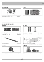
Page 36: ...IO TRANSMITTER SUN Wi Fi DEVICES MASTER Wi Fi RECEIVER CARD TO MANAGE WIRELESS SYSTEM with connector 12 30V ac dc code ACG6094 with terminal block 12 30V ac dc code ACG6099 NOVA Wi Fi PHOTOCELLS WITHOUT WIRES code ACG8037 PAIR OF COLUMS NOVA code ACG8039 VERTIGO Wi Fi WIRELESS PHOTOCELLS SUBSTITUTING THE SAFETY STRIP VERTIGO Wi Fi 8 code ACG8042 VERTIGO Wi Fi 10 code ACG8043 BLOCK Wi Fi KEY SELECT...

Page 37: ...eingebautem mechanischen Anschlag der während der Öffnung anspricht Wird auch der optionale mechanische Anschlag benutzt der während des Schließens anspricht so reduziert sich der maximale Zughub um 30 mm 1 5 5 4 4 3 2 1 TECHNISCHE EIGENSCHAFTEN PRINCE 24V Max Torflügelweite m 3 Max Torgewicht kg 250 Max Hub mm 343 Mittlere Öffnungszeit zirka s 14 Laufgeschwindigkeit m s 0 0134 Stromspannung und f...

Page 38: ... und oder andere Sicherheitseinrichtungen muessen mit den Norm EN12453 uebereinstimmen Anhang A E Photozelle wie Kode ACG8026 Jede 60 70 cm für die ganze Höhe der Spalte des Gatters bis zu einem Maximum von 2 5 m anwenden EN 12445 Punkt 7 3 2 1 NOTENTRIEGELUNG Um das Tor des Modells PRINCE manuell zu bedienen müßen Sie den dafür vorgesehenen Schluessel in das Schloß stecken und ihn 90 entgegen dem...

Page 39: ... 90 13 5 S3 X A 60 110 100 765 90 14 S3 Y A 80 140 110 765 115 17 S3 X B 100 160 110 765 115 18 S3 X B 120 180 110 765 115 19 5 S3 X B 140 210 110 765 115 21 5 S1 Z B 150 220 120 765 115 23 S1 Z B 20 110 140 765 90 17 S1 Y A Für eine korrekte Installation MIT ZWEI MECHANISCHE SPERRVORRICHTUNG 110 90 L Min Max a A max T sec B C D E 1 3 COL ANT 0 100 100 730 90 13 5 S2 X A 20 100 100 730 90 13 5 S2 ...

Page 40: ...ungsweite einzustellen genüngt es die Endschalter A zu verstellen und sie mit Hilfe eines Imbusschlüßels an der Mutterschraube festzuziehen Um die erwünschte Schliessweite einzustellen müssen Sie die Endschalter B verstellen WARTUNG Die Wartungsarbeit nur durch spezialiesierten Fachleuten nach der Ausschliessung der Spannung auszuführen Einmal jährlich sind die Angelzapfen zu schmieren und die vom...

Page 41: ...ZELIMPULS GEMEINSAME ERDUNGSKONTAKTE GEMEINSAME ERDUNGSKONTAKTE 24Vdc 0 8A 15 für ZUBEHÖRE 24Vdc 0 8A 15 für AUTOTEST KONTAKTLEISTE BLINKER 24Vdc 20W LED R 2 2K 1 4W ELEKTROSCHLOSS FUSSGÄNGER KONTAKLEISTE STROMVERSORGUNG 230Vac 50 Hz TRANSFORMATOR M1 M2 T2 24V Kode AC07088 T2 24V CRX Kode AC07089 ...

Page 42: ...FALL SCHLIESSEN SICH DIE FLÜGEL OHNE DIE BEWEGUNG ZU INVERTIEREN TRIMMER RUN TR1 Elektronischer Regler für hohe Geschwindigkeit Mit diesem Trimmer kann die Motorgeschwindigkeit eingestellt werden Standardeinstellung J1 N F Speisung 230 Vac 50 60 Hz extern an der Karte 120V 60Hz auf Anfrage J2 COM Gemeinsame erdungskontakte CLOSE Schließung Impuls Kontakt NA OPEN Öffnungs Impuls Kontakt NA STOP Sto...

Page 43: ...UR EINEM MOTOR MUSS DIP 13 AUF GESTELLT WERDEN ON WÄHREND DER PROGRAMMIERUNG BLEIBT DER STROMSENSOR IMMER AKTIV Das Tor muss vollständig geschlossen sein 1 DIP 2 auf EIN stellen Die LED AnzeigeDL1 beginnt zu blinken 2 Den Schalter PROG drücken M1 öffnet Nach Erreichen des Öffnungs Endanschlages hält der AUTOMATISCHE STROMSENSOR M1 an und speichert Zeit und Stromwerte 3 Den Schalter PROG drücken M1...

Page 44: ...hrend der Öffnungsbewegung gedrückt Wird die Taste bei offenem Tor gedrückt so wird das Tor geschlossen drückt man sie bei geschlossenem Tor führt das zur Öffnung ÖFFNUNGS TASTE COM OPEN Bei stillstehendem Tor steuert diese Taste die Öffnungsfunktion an wird sie während des Schließvorganges gedrückt so wird das Tor wieder geöffnet DIE UHR FUNKTON DER SCHALTTASTE ÖFFNUNG Wenn Sie eine Uhr oder einf...

Page 45: ...d dieser Zeitspanne ist eine Stabilisierung der Funktionsweise des Tores durch Drücken einer beliebigen Befehlstaste möglich ARBEIT IM MANNSBEISEIN IM FALL EINES AUSFALLS DER SICHERHEITEN Wenn die Kontaktleiste ist defekt oder diese arbeit länger als 5 Sekunden oder wenn die Fotozelle defekt ist oder für mehr als 60 Sekunden arbeit die Befehle ÖFFNEN SCHLIESSEN K und FUßGÄNGERZONE TASTE im Mannsbe...

Page 46: ...CG4648 OPTIONEN Für die Anschlüsse und die technischen Daten der Zubehöre verweisen wir auf die entsprechenden Betriebsanleitungen D FEHLER LÖSUNG Nachdem die verschiedenen Verbindungen gelegt sind und Strom angelegt wurde sind alle LEDs ausgeschaltet Die Unversehrtheit der Sicherungen F1 FUSE 1 überprüfen Die Sicherungen mit geleichwerteigen ersetzen F1 T 2A SICHERUNG ZUM TRANSFORMATORSCHUTZ auße...

Page 47: ...dblockierung 12 30V ac dc Kode ACG6099 NOVA Wi Fi FOTOZELLEN OHNE KABEL Kode ACG8037 EIN PAAR FOTOZELLEN STÄNDER NOVA Kode ACG8039 VERTIGO Wi Fi KABELLOSE FOTOZELLE ERSETZT DIE SCHALTLEISTEN VERTIGO Wi Fi 8 Kode ACG8042 VERTIGO Wi Fi 10 Kode ACG8043 BLOCK Wi Fi SCHLÜSSELSCHALTER OHNE KABEL Kode ACG6098 SPARK Wi Fi BLINKER OHNE KABEL Kode ACG7064 SEITENLAGER Kode ACG7042 TOUCH Wi Fi KONTAKTLEISTE O...

Page 48: ...bién el seguro mecánico que interviene durante el cierre opcional la carrera máxima de remolque se reduce de 30 mm DISPOSICIÒN DE LA INSTALACIÒN 1 5 5 4 4 3 2 1 CARACTERÍSTICAS TÉCNICAS PRINCE 24V Longitud máxima de la anta m 3 Peso máx cancela kg 250 Corrido max de arrastre mm 343 Tiempo de abertura s 14 Velocidad de arrastre m s 0 0134 Alimentación e frequenza 24Vdc Potencia nominale a 71 rpm vi...

Page 49: ... dispositivos que limitan las fuerzas entre limites de las normas EN 12453 Appendix A E Fotocélulas como cód ACG8026 Da applicare cada 60 70 cm por toda la altura de la puerta hasta un máximo de 2 5 m EN 12445 punto 7 3 2 1 DESBLOQUEO DE URGENCIA En el caso de falta de corriente para poder accionar la cancela es suficiente introducir la respectiva llave y girarla de 90 en sentido antihorario Fig 3...

Page 50: ... 100 765 90 13 5 S3 X A 60 110 100 765 90 14 S3 Y A 80 140 110 765 115 17 S3 X B 100 160 110 765 115 18 S3 X B 120 180 110 765 115 19 5 S3 X B 140 210 110 765 115 21 5 S1 Z B 150 220 120 765 115 23 S1 Z B 20 110 140 765 90 17 S1 Y A Medidas a respetar CON 2 SEGUROS MECÁNICOS 110 90 L Min Max a A max T sec B C D E 1 3 COL ANT 0 100 100 730 90 13 5 S2 X A 20 100 100 730 90 13 5 S2 X A 40 100 100 730...

Page 51: ... da 8mA con la llave fija n 13 Para obtener el cierre deseado se tendrá que mover el seguro B OPCIONAL bloccandolo come descritto per il fermo A MANTENIMIENTO Estas operaciones deben ser efectuadas exclusivamente por personal especializado y con el motor desconectado de la alimentación eléctrica Todos los años engrasar las bisagras y controlar la fuerza de empuje ejercida por el motorreductor sobr...

Page 52: ...FOTOCÉLULAS PASSO PASSO COMÚN COMÚN 24Vdc 0 8A 15 para ACCESSORIOS 24Vdc 0 8A 15 para AUTOTEST COSTAS INTERMITENTE 24Vdc 20W LED R 2 2K 1 4W CERRADURA ELÉCTRICA PEATONAL COSTAS ALIMENTACION 230Vac 50Hz TRANSFORMADOR M1 M2 T2 24V cód AC07088 T2 24V CRX cód AC07089 ...

Page 53: ... EN ESTE CASO LAS PUERTAS SE DETENDRÁN SIN INVERTIR EL MOVIMIENTO TRIMMER RUN TR1 Regulador electrónico de la alta velocidad Con este trimmer es posible regular la velocidad del motor por defecto se configura al máximo de la velocidad La regulación resulta de gran utilidad pues permite que la automatización sea conforme a las normas europeas en materia de impactos A CONEXIÓN J3 TR2 TR1 J2 J4 F1 FU...

Page 54: ... POSICIÓN ON DURANTE LA PROGRAMACIÓN EL SENSOR DE CORRIENTE ESTÁ SIEMPRE ACTIVO La cancela debe estar completamente cerrada 1 Coloque el DIP 2 en posición ON El led DL1 emitirá parpadeos breves 2 Presione el pulsador PROG M1 se abre Una vez alcanzado el seguro mecánico de apertura el SENSOR DE CORRIENTE detiene M1 con memorización del tiempo y de la corriente 3 Presione el pulsador PROG M1 se cier...

Page 55: ...sores magnéticos están programados en el modo de IMPULSO de lo contrario pueden activar el movimiento de la puerta sin tener activos los elementos de seguridad PULSADOR DE MANDO PASO PASO COM K BUTTON Si DIP 6 en OFF Ejecute un mando cíclico de órdenes abre stop cierra stop abre etc Si DIP 6 en ON Ejecute la apertura con cancela cerrada Si se acciona durante el movimento de apertura no tiene efect...

Page 56: ...de seguridad se estropea o se queda empeñada por mas de 60 segundos los comandos ABRE CIERRE K BUTTON y el PEATONAL funcionaràn solo a hombre presente El signal de activación de este funcionamiento serà indicado por el LED de programacion que relampaguea En este funciòn será aconsentido el apertura y el cierre solo manteniendo apretados los pulsadores de comandos El comando radio y el cierre autom...

Page 57: ...do OPCIONALES Para las conexiones y datos técnicos de los accesorios consultar los manuales respectivos E S DEFECTO SOLUCIÓN Después de haber efectuado varias conexiones y haber dado tensión todos los led están apagados Verifique la integridad de los fusibles F1 FUSE 1 En caso de fusible interrumpido utilice únicamente uno de valor adecuado F1 T 2A FUSIBLE DE PROTECCIÓN TRANSFORMADOR externo a la ...

Page 58: ...ABLES con enchufe 12 30V ac dc cód ACG6094 con regleta 12 30V ac dc cód ACG6099 NOVA Wi Fi FOTOCÉLULAS SIN CABLES cód ACG8037 PAR DE COLUMNAS NOVA cód ACG8039 VERTIGO Wi Fi FOTOCÉLULAS SIN CABLES PARA REMPLAZAR A LA COSTA VERTIGO Wi Fi 8 cód ACG8042 VERTIGO Wi Fi 10 cód ACG8043 BLOCK Wi Fi SELECTOR DE LLAVE SIN CABLES cód ACG6098 SPARK Wi Fi INTERMITENTE SIN CABLES cód ACG7064 SOPORTE LATERAL cód ...

Page 59: ...paragraphe 2 de la Directive machines 2006 42 CEE et de ses modifications successives Sa mise en service est interdite avant que l installation ait été déclarée conforme aux dispositions prévues par la Directive This product can not work alone and was designed to be fitted into a system made up of various other elements Hence it falls within Article 6 Paragraph 2 of the EC Directive 2006 42 Machin...

Page 60: ...8088 Fermo meccanico in chiusura PRINCE BA01046 Serie access cilind PRINCE BA01076 Sacch access PRINCE CAL1157 Semiguscio inferiore CAL1158 Semiguscio superiore CCA1263 Gruppo Forcella Perno CCA1351 Piastra cancello CEL1457 Blocca cavo CME5235 Chiocciola bronzo CME6085 Forcella posteriore CME2125 Boccola vite senza fine CME9056 Vite s fine CMO1286 Mot PRINCE EPIC MBT 24V CPL1127 Supporto motore 24...

Reviews: