Pag. 17 di 28
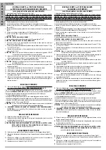
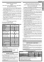
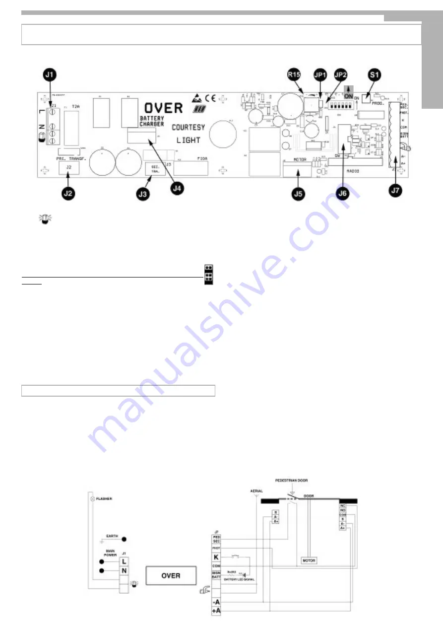
ELECTRONIC BOARD OVER
J1 =>
L - N
Feeding 230 Vac 50/60 Hz (on request 120V/60Hz)
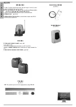
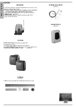
Flashlight Connection at 230Vac 40W (code ACG7059)
(on request 120V 40W code ACG7060)
J2 =>
PRI. TRANSF.
Connector for primary transformer
J3 =>
SEC.TRANSF.
Connector for secondary transformer
J4 =>
BATTERY
Connector for battery recharge card (code ACG4660)
CHARGER
J5 =>
MOTOR
Connection MOTOR and ENCODER (carried out in the factory)
J6 =>
SW
Connector dedicated to the programming in the factory.
DO NOT TOUCH THE JUMPERS WHICH ARE IN THE POSITION INDICATED IN THE
PICTURE
J7 => Controls and Fittings Feeding
1
PED. SEC.
Contact for security Micro for pedestrian door (NC)
2
PHOT.
Photoelectric cells contact (NC)
3
K
Single Impulse Contact (NA)
4
COM.
Common Contacts
5
SIGN. BATT.
Battery State led connection (12Vdc)
6
AERIAL
Cable shielding aerial connection
7
AERIAL
Aerial central cable connection
8
A-
Negative for Fittings feeding (-24Vdc)
9
A+
Positive for Fittings Feeding (+24Vdc)
U7 =>
RADIO
Radio Receiver Mode 433,92 MHz
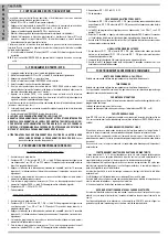
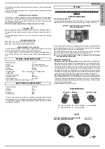
B - ADJUSTING THE MICRO-SWITCHES
DIP 1
CHECK MOTOR ROTATION DIRECTION (ON) (POINT C)
DIP 2
TIMES PROGRAMMING (ON) (POINT D)
OPERATING MICRO-SWITCHES
DIP 1-2
Read in /cancellation radio codes for motor control
(DIP 1 ON followed by DIP 2 ON)
DIP 2-1
Read in/cancellation radio codes for courtesy light control
(DIP 2 ON followed by DIP 1 ON)
DIP 3
Waiting time before automatic closing (ON) (max 5 min.)
DIP 4
Photoelectric cells always active (OFF) – Photoelectric cells active only in closing phase (ON)
DIP 5
Release Facilitation (ON active).
DIP 6
Pre-flashing (ON) – Normal flashing (OFF)
JP1 =>
Exclusion encoder as safety (OFF encoder activated - ON deactivated)
JP2 =>
If closed,
the card is for the motor COMET 60S depicted.
To execute the configuration for the motor COMET 80S,
open
the two soldering
pads cutting the trace.
S1 =>
PROG. Button for the programming.
R 15=> Slow speed electronic regulation
The slow speed regulation is carried out by operating on the R15 Trimmer, through which the
output voltage at the ends of the motor can be changed (rotating clockwise the speed increases).
The regulation is carried out to determine the correct speed during the opening and closing ending
phase according to the structure of the door or in the presence of slight frictions which could
compromise the correct working of the system.
LED SIGNALLINGS
DL1 Encoder operation check (red)
DL2 Programming activated (red)
DL3 Photoelectric cells connection (NC) (red)
DL4 Pedestrian door safety (NC) (red)
RELAY
K1 - Power Relay which controls the flashlight
K2 - Power relay which controls the courtesy lamp
K3 - Power relay which enables the opening
K4 - Power relay which enables the closing
OMNIFET
TR4 - Power Omnifet which controls both the opening and the closing
FUSES
F1 - 2A protection fuse for primary
F2 - 10A protection fuse for the motor
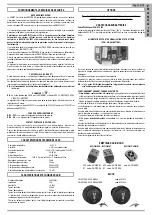
COURTESY LIGHT
Courtesy light 230Vac 40W max (on request 120V 40W)
Code BC07072
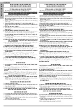
A - ELECTRICAL CONNECTIONS
E
N
G
L
I
S
H


