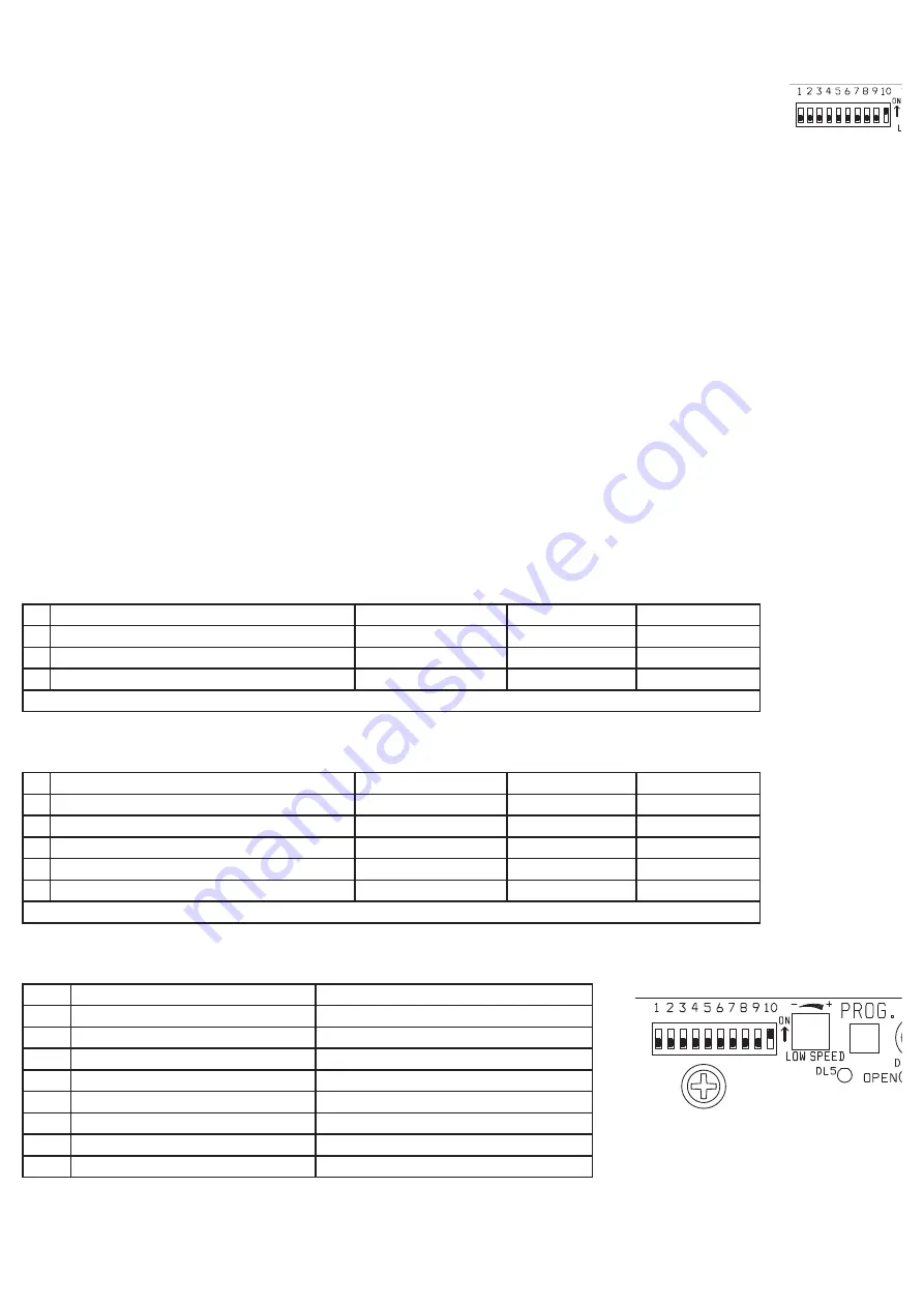
4° Checking manoeuvre direction, force adjustment and slowing down when approaching
AGAIN: Invert the motor wires as well as LSO with LSC if the gate opens to the left.
Note
: In this phase the gate moves only by constantly pressing the PROG button and is the step-by-step type which means that each time the PROG button is
pressed we have an open-stop-close-stop-open … manoeuvre.
To confirm that the configuration is good check the LEDs as described below.
a) Set the micro switches DIP 1-2-3-4-5-6-7-8-9 at OFF and DIP 10 at ON.
b) Unblock the motor. Position the gate halfway. Block the motor.
c)
Set DIP 1 at ON
(the DL5 LED flashes rapidly)
d) Press the PROG button (the red DL7 “CLOSE” LED turns on and the gate must close)
e) After 3 seconds the slow-down function is activated and slow speed can be regulated with the LOW SPEED trimmer.
f) The cam presses the end run when closing has ended and stops the motor (The DL7 “CLOSE” LED turns off).
g) Release the PROG. button
h) Press the PROG button again (the green DL6 “OPEN” LED turns on and the gate starts to open)
i) The end run stops the motor when the gate is completely opened (DL6 “OPEN” turns off)
l)
Place DIP 1 back at OFF
and pass on to point 5°
5° Programming working and waiting times before having automatic closing.
IMPORTANT:
Bridge COM-PHOT and COM-STOP if the safety devices are not installed. The DL1 and DL2 LEDs must be on.
If a LED is off it indicates a safety device failure or no connection and gate movement is blocked.
a) Rotate the C.S. (current sensor) trimmer completely clockwise.
b) Set
DIP 2 on ON
(the DL5 LED flashes slowly)
c) Press the PROG button briefly (the gate closes, it stops when it comes up against the stop, it waits 2 seconds and then opens automatically, stopping against
the end-of-opening limit switch). Once the gate has completed the opening manoeuvre the control panel starts counting the waiting time before the gate starts
closing automatically.
Note: Even if the automatic closing function is not active (DIP 3 OFF), it must still be memorized.
d) Wait for the length of time wanted and then press the PROG to store the waiting time and start the gate closing.
e) The gate is closed. DL5 stops flashing. The times are stored. Put
DIP 2 back on OFF
.
6° Adjustment of Current Sensor (active if DIP 10 ON)
This sensor has the task of inverting motor movement both when opening and closing should the gate hit an obstacle.
Rotating the C.S. trimmer clockwise, greater force must be used to invert gate movement. If the C.S. trimmer is rotated anti-clockwise, the sensitivity of the
motor increases and a small bit of force is enough for inversion.
7° Programming the remote control
SINGLE CHANNEL RECEIVER
- Plug either an ACG5055 or ACG5047 radio receiver onto connector J5 (this lets you control the electronic panel directly with
the first channel of the remote control).
Action
LED confirm
Reaction
Remarks
DL1 and DL2 flash
1°
Press briefly the small
button P
on the receiver
DL1
flashes
release
P
go to step 2°
2°
Press key
A on the remote control
for 1.5 seconds
DL2
flashes once
does not transmit
Finished
Let
DL2
flash 10 times or press
P on the receiver
to exit programming
TWO-CHANNEL RECEIVER
- Plug either an ACG5051 or ACG5048 radio receiver onto connector J5 (this lets you control the electronic panel directly with the
first channel of the remote control).
Connect the second relay R2 of the radio receiver to COM/PED so the pedestrian opening or other device can be radio controlled.
Action
LED confirm
Reaction
Remarks
DL1 and DL2 flash
1°
Press briefly the small
button P
on the receiver
DL1
flashes
release
P
go to step 2°
2°
Press key
A on the remote control
for 1.5 seconds
DL2
flashes once
does not transmit
go to step 3°
3°
Press briefly the small
button P
on the receiver
DL2
flashes
release
P
go to step 4°
4°
Press key
B on the remote control
for 1.5 seconds
DL1
flashes once
does not transmit
Finished
Let
DL2
flash 10 times or press
P on the receiver
to exit programming
8° Customising the configuration
The configuration can be modified by moving the various microswitches
Microswitches ON
Microswitches OFF
DIP3
Automatic closing activated
Automatic closing not activated
DIP4
RADIO control ineffective for opening
RADIO control open-stop-close-stop.....
DIP5
K-BUTT control ineffective for opening
K-BUTT control open-stop-close-stop.....
DIP6
Photocells active only for closing
Photocells always active
DIP7
-
-
DIP8
3- second pre-flash
Motor and flasher start together
DIP9
Automatic pedestrian closing activated
Automatic pedestrian closing not activated
DIP10 Current sensor activated
Current sensor not activated
IMPORTANT: The system must comply with all the standards and Directives currently in force.


