3
5
4
4
DIN 18650
BS 7036
EN 16005
3,50 m
3 m
2,50 m
2 m
d max = 2,5 m
d max = 3 m
3,50 m
3 m
2,50 m
2 m
max.
9 cm**
+
+
+
OR
WID
TH
Additional
adjustments
are possible by
LCD or remote
control
(see p. 5)
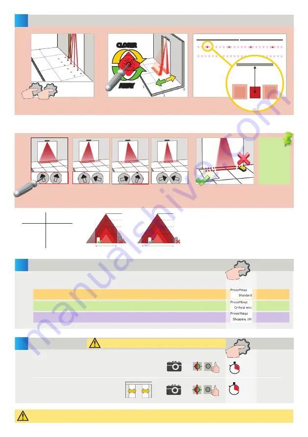
Part of the detection field can be masked to reduce it.
The arrow position determines the width of the detection field.
INFRARED SAFETY FIELD
CLOSER
AWAY
If necessary, adjust the IR-curtain
angle (from -7° to 4°, default 0°).
Activate the visible* spots to verify the
position of the IR-curtain.
ANGLE
SETUP
TEST THE GOOD FUNCTIONING OF THE INSTALLATION BEFORE LEAVING THE PREMISES!
SETTINGS
* Visibility depends on external conditions. When spots are not visible, use the Spotfinder to locate the curtains.
** The distance between the inner curtain of the inside door sensor and the inner curtain of the outside door sensor should always
be smaller than 20 cm. The distance to the door leaf depends therefore on the thickness of the door leaf.
The size of the detection field varies according to the moun-
ting height and the settings of the sensor.
The full door width must be covered.
STANDARD
:
standard in- and outdoor installations
CRITICAL
ENVIRONMENT
:
critical installations due to surroundings or weather
SHOPPING
STREET
:
installations in narrow streets with pedestrian traffic
Mounting
height
Detection
width
2.00 m
2.20 m
2.50 m
3.00 m
3.50 m
2.00 m
2.20 m
2.50 m
d max
d max
Choose one of the following presettings or adjust the sensor manually (see p.5):
Always verify the actual detection field width
with a piece of paper and not the Spotfinder,
which detects the whole emitted field.
3.50 m
3 m
2.50 m
2 m
d max = 2.5 m
3.50 m
3 m
2.50 m
2 m
DOOR
SETUP 1 (QUICK)
SETUP 2 (ASSISTED)
2 s
4 s
STEP OUT OF THE INFRARED FIELD!
reference picture
test of full door cycle +
reference picture


