background image


Adjustment Of The Feed Gap 

The  correct  Feed  Gap  setting  of  the  Central  Feed  Roller  assemblies  is  vitally 
important to the smooth function of  the machine.    After extremely long-term usage, 
the rubber components of both the Feed Roller and the Friction Roller may be subject 
to natural wear.    Under this condition, the Feed Gap may become too wide and, as a 
result, Error Codes will be generated and note feeding will become erratic. 


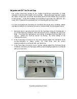
To check and adjust the Feed Gap to counteract this simple wear condition, please 
operate according to the following procedure, combined with the photograph below: 


1.  Manually  insert a  genuine  banknote  into  the  Feed  Gap  and pull  it backwards, if 

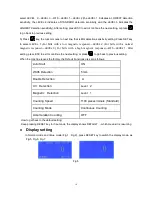
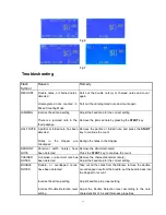
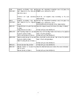
you did not feel any resistance while removing the note, it indicates the gap is too 
wide.    If you feel the resistance is very strong,  it indicates the Feed Gap is too 
narrow.    (When  the  machine  leaves  our  factory,  the  initial  setting  of  the 
Thickness Dial is 2). 

2.  If  the  Feed  Gap  is  found  to  be  too  wide,  please  adjust  the  Thickness  Knob 

counter-clockwise  to  slowly  reduce  the  Feed  Gap  until  the  proper 
slipping-resistance is achieved with your banknote. 

3.  If  the  Feed  Gap  is  found  to  be  too  narrow,  please  adjust  the  Thickness  Knob 

clockwise to increase the feed gap until the proper slipping-resistance is achieved 
with your bank note. 


Feed Gap Adjustment Knob 


Summary of Contents for BC2000-US Series

Page 1: ...BC2000 US Series Currency Counter Operation Instructions ...

Page 2: ...y Function 5 Precautions 6 Operating 6 Start 6 Adjust the Note Guides 7 Working Mode Selection 7 Select the denomination banknotes 7 Speed Selection 7 Batch Setting 8 Accumulation 8 Notes Setting 8 Operation 9 Function Setting 9 Display Setting 10 Troubleshooting 11 Daily Maintenance 12 ...

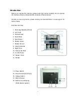
Page 3: ...r local distributor or sales agent for further advice Machine Overview 1 Feed Gap Adjustment Knob 2 Left Cover 3 Friction Roller 4 Feed Roller 5 Drum Roller 6 Stacker Vanes 7 Stacker Sensor 8 Carrying Handle 9 Right Cover 10 Note Guide Plate 11 Control Panel 12 Stacker Cover 13 Stacker 14 Power Switch 15 Power Socket With Fuse 16 Voltage Switch 17 RS232 Socket 18 Remote Count Display RCD Socket op...
Page 4: ...ed with the photograph below 1 Manually insert a genuine banknote into the Feed Gap and pull it backwards if you did not feel any resistance while removing the note it indicates the gap is too wide If you feel the resistance is very strong it indicates the Feed Gap is too narrow When the machine leaves our factory the initial setting of the Thickness Dial is 2 2 If the Feed Gap is found to be too ...

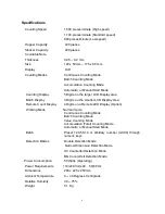
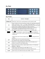
Page 5: ...3 Digits on the smaller LCD Display area Remote Count Display 4 Digits on a Remote LED Display Option Working Mode Normal mode Continuous Counting Mode Batch Counting Mode Value Counting Mode Accumulation Total Counting Mode Automatic or Manual Start Mode Batch Preset 100 50 10 or arbitrary number 0 999 through numeric keys Detection Modes Double Detection Mode Narrow Dimension Detection Mode UV C...

Page 6: ...you can turn on off the buzzer Press key to increase the contrast of LCD press key to decrease the contrast There are 7 levels to select 0 6 the default setting is 4 After setting press CLEAR to exit Press SET key to enter into menu interface press to change the current selection SET Press SET key to enter into Function setting interface Then press SET key to change function setting condition ESC ...

Page 7: ...cting your currency counter with the local domestic mains supply please ENSURE that your local mains voltage is correctly shown by the Switch either 110 or 220 volts mounted on the rear of the machine If the indication is incorrect ensure the machine is disconnected with the electrical source Then the Switch can be easily moved to the correct position using a suitable blunt implement DO NOT drop a...

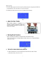
Page 8: ...e Guides After function setting is completed it is important to adjust the distance between the two Note Guides according to the length of the notes to be counted Working Mode Selection Users can select the mode as in needed with the procedures as follow Press the VALUE key to change between Value mode as is in Fig 2 and Normal mode as is in Fig 1 Fig 2 Select the denomination banknotes In Value c...

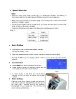
Page 9: ... min SP H high 1500pcs min Batch Setting Press BATCH key to select default Batch Number 100 50 10 OFF 100 Input your desired random number 0 999 simply by press the numeric keys Pressing CLEAR key the displayed batch number can be cleared and turn off the function Accumulation Press ADD key to turn the function ON or OFF Under Normal mode the counting number will be accumulated on the last counted...

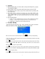
Page 10: ...nction Setting In Normal mode and Value mode Fig 1 Fig 2 press SET key to enter into function setting menu interface as Fig 4 Press ESC to go back to working mode Fig 4 When the machine enters into function setting menu press or SET key to change setting 1 State mode setting press SET to select ON OFF ON in turn After setting press ESC to exit setting or continue the next setting 2 Press key the c...

Page 11: ... response LEVEL 3 For bills with a high magnetic response OFF LEVEL 1 After setting press ESC to exit or continue the next setting or press to go back to previous setting When the machine leaves the factory the Default Functions are set as follows Auto Start ON Width Detection 5 mm Double Detection A UV Detection Level 2 Magnetic Detection Level 1 Counting Speed 1100 pieces minute Standard Countin...

Page 12: ...d note and press the START key to continue the count Realign the notes in the Hopper NARROW NOTE Abnormal width note s have been detected Remove the abnormal note s Press the START key to continue the count CHAINED NOTES A chained or abnormal note has been detected Remove the chained abnormal note s Adjust the Feed Gap for the correct setting DOUBLE NOTES Double or overlapped notes have been detec...

Page 13: ... is broken Clean the Hopper Sensor and remove the notes in Hopper Contact with your local distributor ERR LCS Left Counting Sensor is covered by dust or jammed notes Left Counting Sensor is broken Clean the Left Counting Sensor and remove the jammed notes in counting passage Contact with your local distributor ERR RCS Right Counting Sensor is covered by dust or jammed notes Right Counting Sensor i...

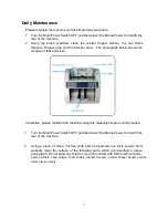
Page 14: ...devices In addition please maintain the machine using this relatively simple monthly routine 1 Turn the Main Power Switch OFF and disconnect the Mains Power Cord with the rear of the machine 2 Using a piece of clean lint free cloth and an approved non toxic solvent fluid carefully clean the surface of the following parts which are identified in above photograph Do not allow any fluid to come into ...

Reviews: