background image

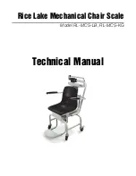
Rice Lake Mechanical Chair Scale

Model RL-MCS-LB, RL-MCS-KG

Technical Manual

PN 172686

Summary of Contents for 172098

Page 1: ...Rice Lake Mechanical Chair Scale Model RL MCS LB RL MCS KG Technical Manual PN 172686 ...

Page 2: ...Rice Lake Mechanical Chair Scale Warranty 12 Technical training seminars are available through Rice Lake Weighing Systems Course descriptions and dates can be viewed at www ricelake com training or obtained by calling 715 234 9171 and asking for the training department Rice Lake Weighing Systems All rights reserved Specifications subject to change without notice Rice Lake Weighing Systems is an IS...

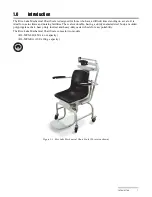
Page 3: ...ng a sturdy enameled steel body a molded polypropylene chair heavy duty footrest and heavy duty caster wheels for easy portability The Rice Lake Mechanical Chair Scale comes in two models RL MCS LB 450 x 4 oz capacity RL MCS KG 200 x 100 g capacity Manuals can be viewed and downloaded from the Rice Lake Weighing Systems website at www ricelake com health Figure 1 1 Rice Lake Mechanical Chair Scale...

Page 4: ...porting patients To avoid cross contamination the scale should be cleaned regularly Do not allow minors children or inexperienced persons to operate this scale Do not jump on the scale Do not use in the presence of flammable materials People who are physically frail should always be assisted by another person when getting on and off the scale Do not use the scale on slippery surfaces such as a wet...

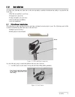
Page 5: ...n The pillar beam comes detached from the scale base and must be attached prior to use The following tools will be needed to assemble the pillar and beam to the scale base Phillips head screwdriver Multi purpose tool included Figure 2 1 Pillar and Beam Components Use the following steps to attach the pillar and beam to the scale base 1 Lock the casters on the frame to keep the unit from rolling du...

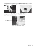
Page 6: ... Platform Shown 3 Remove the eight screws from the scale base and retain for installation See Figure 2 4 Figure 2 4 Remove Screws from Scale Base There is a steelyard rod located inside the pillar 4 Remove the twist ties used to secure the steelyard rod during shipment Figure 2 5 Remove Twist Tie from Steelyard Rod 5 Move the pillar onto the base ensuring that the Rice Lake label on the pillar sho...

Page 7: ...the ring in the scale bottom Latch the hook onto the D shaped ring Figure 2 6 Attach Steelyard Rod to the Scale Base D Ring 7 Set the pillar beam assembly on the scale base assembly See Figure 2 7 8 Secure with the screws and star washers Figure 2 7 Pillar Beam Assembly on Scale Base Steelyard rod not shown Steelyard rod hook D Shaped ring Retaining screws ...

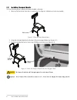
Page 8: ...2 Align the transport handle to both sides of the scale support frame see Figure 2 9 3 Insert and tighten the four screws using a Phillips screwdriver see Figure 2 9 Figure 2 9 Secure the Transport Handle to the Scale Support Frame The transport handle should fit snuggly against the scale support frame Do not transport the scale while someone is on it the scale is not designed for transporting pat...

Page 9: ...ded chair on the scale support frame platform do not fasten the screws at this time 3 Remove screws from the chair frame and retain them for installation 4 Tilt the chair forward Figure 2 11 Tilt the Chair Upward Before Installing the Footrest Assembly 5 Slide the footrest assembly onto the chair scale base aligning the holes to the chair scale frame Four screws on scale support frame only one scr...

Page 10: ...12 Figure 2 12 Install Footrest Assembly 6 Secure the footrest assembly to the chair frame 7 Tilt the chair assembly back and secure four screws Figure 2 13 Molded Chair to the Platform Base 2 4 Arm Rest Installation Detachable arm rests that can be rotated up and down for easy patient access Figure 2 14 Detachable Arm Rest for the Mechanical Chair Scale Note Secure screws only one shown ...

Page 11: ...s to the bolt holes located on the back of the chair Figure 2 15 Secure Arm Rest to Chair 2 Secure one of the arm rests to the chair using two bolts and the 5 mm Allen wrench included Figure 2 16 Secure Arm Rests to the Molded Chair 3 Repeat steps 1 2 for the other arm rest Figure 2 17 Secured Arm Rests Bolt holes ...

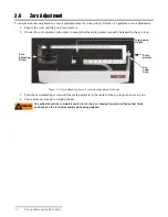
Page 12: ...pointer is equally balanced in the eye loop Figure 3 1 Zero Adjusting Screw Location pound model shown 3 Turn the zero adjusting screw until the scale pointer is in the center of the eye loop when set to zero 4 The scale is now ready to weigh patients The patient should be completely seated in the chair not leaning forward and having feet firmly positioned on the footrest assembly while being weig...

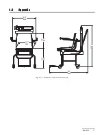
Page 13: ...Appendix 11 4 0 Appendix Figure 4 1 Mechanical Chair Scale Dimensions 360 0 14 2 375 0 14 8 547 0 21 5 400 0 15 7 975 4 38 4 908 0 35 7 ...

Page 14: ...xists and was not caused by accident misuse neglect alteration improper installation improper repair or improper testing RLWS shall be the sole judge of all alleged non conformities Such equipment has not been modified altered or changed by any person other than RLWS or its duly authorized repair agents RLWS will have a reasonable time to repair or replace the defective equipment Buyer is responsi...

Reviews: