Installation and Wiring
11
2.5
Intrinsic Safety Barriers
The IQ plus 310A XPCD is designed to be used by personnel already trained and familiar with intrinsic safety
barriers. They are designed to self destruct if a dangerous condition occurs.
Note:
If you are not trained to work on this equipment, stop. Call you scale dealer for assistance.
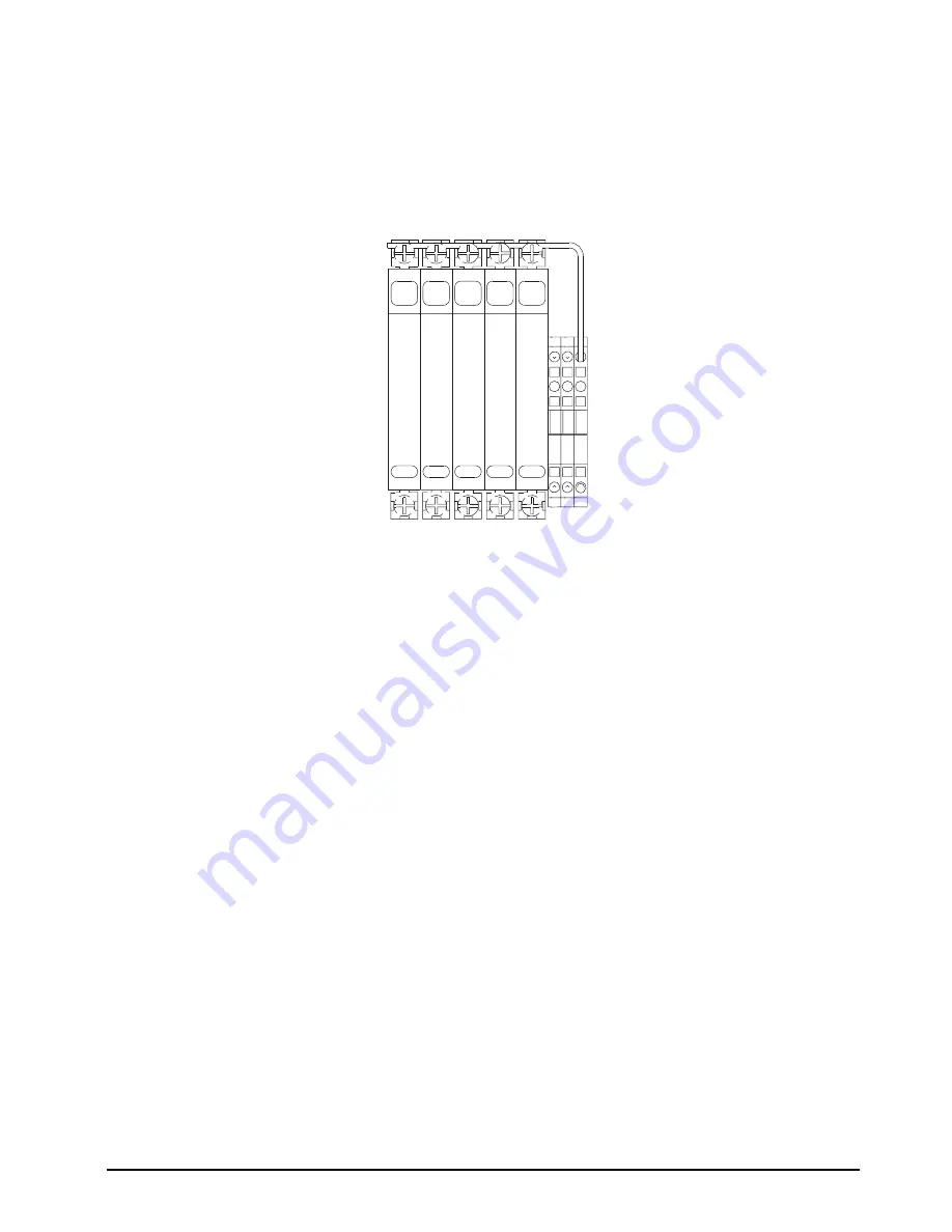
All intrinsic safety barriers have five terminals (shown below).
Figure 2-4. Intrinsic Safety Barrier
Terminals three and four are the intrinsically safe connections. Devices in the hazardous location are connected
to these terminals. Terminals one and two are the non-intrinsically safe connections for devices within the
non-hazardous location. The maximum source voltage applied to these terminals under a fault condition must not
exceed 250 V rms.
Along with the four terminals mentioned above, two additional screw terminals are provided, one on each side of
the barrier.
They are directly attached to the barrier mounting/grounding system and can be used to establish a redundant
ground system or for terminating shields. On single channel barriers they are also internally connected to
terminals two and four.
Since a common housing is shared between single, dual, and application dedicated barriers, refer to the
schematic printed on the side of each barrier to determine the designation of the floating and grounded terminals.
If an instrinsic safety barrier self destructs, do not replace it. Find out what caused the problem. Do not assume
the problem can only be in the indicator.
Only when the problem is corrected should a barrier be replaced with the exact same brand and type.
2.5.1
Intrinsic Safety Grounding
Special attention must be given to the grounding system. Without a proper earth ground system, intrinsic safety
barriers will not provide voltage protection. They must therefore be grounded to a designated grounding
electrode that references the original power source and instrumentation within the non-hazardous location. This
source of ground must be less than 1
Ω
from the true earth ground.
+SENSE
-SENSE
-SIGNAL
+SIGNAL
+EXCIT
A
TION
RS232 TXD
-EXCIT
A
TION
RS232 GND
3
4
3
4
3
3
4
4
1
2
1
2
1
1
2
2
2
1
4
3
1
2
DISCONTINUED


