background image

36

IQ plus 350 Installation Manual

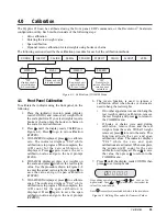
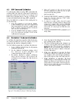
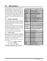
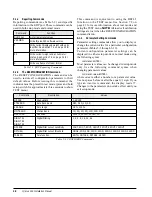
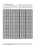
7.4

ASCII Character Chart

Use the decimal values for ASCII characters listed in
Tables 7-4 and 7-5 when specifying print format
strings on the IQ plus 350 PFORMT menu. The actual
character printed depends on the character mapping
used by the output device. 

The IQ plus 350 can send or receive any ASCII
character value (decimal 0–255), but the indicator
display is limited to numbers, upper-case, unaccented
letters, and a few special characters. Characters that
can be shown on the IQ plus 350 display are indicated
by shading in the decimal value columns in Table 7-4.

Table 7-4. ASCII Character Chart (Part 1)

Control

ASCII

Dec

Hex

ASCII

Dec

Hex

ASCII

Dec

Hex

ASCII

Dec

Hex

Ctrl-@

NUL

00

00

space

32

20

@

64

40

`

96

60

Ctrl-A

SOH

01

01

!

33

21

A

65

41

a

97

61

Ctrl-B

STX

02

02

34

22

B

66

42

b

98

62

Ctrl-C

ETX

03

03

#

35

23

C

67

43

c

99

63

Ctrl-D

EOT

04

04

$

36

24

D

68

44

d

100

64

Ctrl-E

ENQ

05

05

%

37

25

E

69

45

e

101

65

Ctrl-F

ACK

06

06

&

38

26

F

70

46

f

102

66

Ctrl-G

BEL

07

07

39

27

G

71

47

g

103

67

Ctrl-H

BS

08

08

(

40

28

H

72

48

h

104

68

Ctrl-I

HT

09

09

)

41

29

I

73

49

i

105

69

Ctrl-J

LF

10

0A

*

42

2A

J

74

4A

j

106

6A

Ctrl-K

VT

11

0B

+

43

2B

K

75

4B

k

107

6B

Ctrl-L

FF

12

0C

,

44

2C

L

76

4C

l

108

6C

Ctrl-M

CR

13

0D

-

45

2D

M

77

4D

m

109

6D

Ctrl-N

SO

14

0E

.

46

2E

N

78

4E

n

110

6E

Ctrl-O

SI

15

0F

/

47

2F

O

79

4F

o

111

6F

Ctrl-P

DLE

16

10

0

48

30

P

80

50

p

112

70

Ctrl-Q

DC1

17

11

1

49

31

Q

81

51

q

113

71

Ctrl-R

DC2

18

12

2

50

32

R

82

52

r

114

72

Ctrl-S

DC3

19

13

3

51

33

S

83

53

s

115

73

Ctrl-T

DC4

20

14

4

52

34

T

84

54

t

116

74

Ctrl-U

NAK

21

15

5

53

35

U

85

55

u

117

75

Ctrl-V

SYN

22

16

6

54

36

V

86

56

v

118

76

Ctrl-W

ETB

23

17

7

55

37

W

87

57

w

119

77

Ctrl-X

CAN

24

18

8

56

38

X

88

58

x

120

78

Ctrl-Y

EM

25

19

9

57

39

Y

89

59

y

121

79

Ctrl-Z

SUB

26

1A

:

58

3A

Z

90

5A

z

122

7A

Ctrl-[

ESC

27

1B

;

59

3B

[

91

5B

{

123

7B

Ctrl-\

FS

28

1C

<

60

3C

\

92

5C

|

124

7C

Ctrl-]

GS

29

1D

=

61

3D

]

93

5D

}

125

7D

Ctrl-^

RS

30

1E

>

62

3E

^

94

5E

~

126

7E

Ctrl-_

US

31

1F

?

63

3F

_

95

5F

DEL

127

7F

Summary of Contents for IQ plus 350

Page 1: ...43544 IQ plus 350 Digital Weight Indicator Version 1 0 Installation Manual ...

Page 2: ......

Page 3: ...nt Ticket 3 2 0 Installation 4 2 1 Unpacking and Assembly 4 2 2 Enclosure Disassembly 4 2 3 Cable Connections 4 2 3 1 Load Cells 5 2 3 2 Serial Communications and Digital Inputs 6 2 3 3 Analog Output 7 2 4 Analog Output Module Installation 7 2 5 Enclosure Reassembly 7 2 6 Board Removal 7 2 7 Replacement Parts 8 3 0 Configuration 12 3 1 Configuration Methods 12 3 1 1 Revolution Scaleware Configurat...

Page 4: ...ing Print Formats 32 6 2 1 Using the EDP Port 32 6 2 2 Using the Front Panel 33 6 2 3 Using Revolution Scaleware 33 7 0 Appendix 34 7 1 Error Messages 34 7 1 1 Displayed Error Messages 34 7 1 2 Using the XE EDP Command 34 7 2 Status Messages 35 7 2 1 Using the P EDP Command 35 7 2 2 Using the ZZ EDP Command 35 7 3 Continuous Output Stream Format 35 7 4 ASCII Character Chart 36 7 5 Conversion Facto...

Page 5: ...nter port for output only RS 232 and 20 mA current loop communications at up to 9600 bps Optional analog output module provides 0 10 VDC or 4 20 mA tracking of gross or net weight values Available in 115 VAC and 230 VAC versions The IQ plus 350 is NTEP certified and Measurement Canada approved for Classes III III HD and III L at 10 000 divisions See Section 7 9 on page 43 for detailed specificatio...

Page 6: ...ed weight is a net weight Entry Mode or Nicht Geeicht The indicator is not in normal mode The Entry Mode or Nicht Geeicht annunciator is shown when the indicator is placed in setup or test mode The symbol displayed depends on indicator configuration Scale is at standstill or within the specified motion band Some operations including tare functions and printing can only be done when the standstill ...

Page 7: ...ay 1 4 3 Zero Scale 1 In gross mode remove all weight from the scale and wait for the standstill annunciator 2 Press the ZERO key The center of zero annunciator lights to indicate the scale is zeroed 1 4 4 Acquire Tare 1 Place container on scale and wait for the standstill annunciator 2 Press the TARE key to acquire the tare weight of the container 3 Net weight is displayed and the annunciator lit...

Page 8: ...5 on page 9 Six neoprene washers PN 45042 for backplate screws included in the parts kit Four rubber bumpers feet for the tilt stand PN 42149 Five cable ties PN 15631 2 2 Enclosure Disassembly The indicator enclosure must be opened to connect cables for load cells communications digital inputs and analog output The IQ plus 350 has no on off switch Before opening the unit ensure the power cord is d...

Page 9: ... and JP2 on When connections are complete reinstall connector J1 on the board and use two cable ties to secure the load cell cable to the inside of the enclosure as shown in Figure 2 2 SW1 J5 J7 JP4 J1 J4 ANALOG OUTPUT F1 LOAD CELL CONNECTOR SERIAL COMM DIGITAL IN KEYPAD CONNECTOR F2 JP7 LOCATION OF INSTALLED ANALOG OUTPUT MODULE Setup Switch Serial Communications Cable to J4 Connector Load Cell C...

Page 10: ...hardware Use the DIG IN menu to configure the digital inputs Figure 2 3 IQ plus 350 CPU and Power Supply Board Port J4 Pin Label Function EDP Port 1 EDPT RS 232 TxD 2 GND RS 232 Ground 20 mA OUT 3 EDPR RS 232 RxD Printer Port 4 PRMA 20 mA OUT 5 PRT RS 232 TxD Digital Inputs 6 IN2 Digital Input 2 7 IN1 Digital Input 1 Table 2 2 J4 Pin Assignments C5 C4 L2 L1 C3 C54 C49 C46 C15 C6 C18 C2 C14 C8 C61 ...

Page 11: ...ust remove the IQ plus 350 CPU board use the following procedure 1 Disconnect power to the indicator Loosen cord grips and remove backplate as described in Section 2 2 on page 4 2 Unplug connectors J1 load cell cable J4 serial communications and digital inputs J7 keypad ribbon cable and JP4 setup switch If an analog output board is installed disconnect the analog output cable See Figure 2 2 on pag...

Page 12: ... 2 7 on page 10 15 42104 7 position screw connectors for J1 J4 2 Figure 2 6 on page 10 16 30342 Wing knobs for tilt stand 2 Figure 2 5 on page 9 17 29635 Tilt stand 1 18 15144 Nylon washers for tilt stand 1 4x1x1 16 2 20 15134 Lock washers No 8 4 21 39018 Bezel 1 Figure 2 9 on page 11 22 39045 Overlay membrane panel 1 Figure 2 9 on page 11 23 39033 Enclosure 1 24 14862 Screws 8 32NC x 3 8 4 Figure...

Page 13: ...Installation 9 Figure 2 5 IQ plus 350 Backplate and Tilt Stand Assemblies 4 10 11 12 6 5 8 16 17 18 24 4X 7 To Line Filter 26 20 4X B See Line Filter and Ground Post Assembly ...

Page 14: ... 7 Line Filter Assembly Figure 2 8 Ground Post Assembly 2 15 To setup switch 3 4X 1 9X A 30 8X J1 J4 AC power in from line filter AC input to CPU board JP7 13 29 12 Setup switch connection to JP4 on CPU board 28 26 Ground Post Assembly 31 To power cord To line filter To backplate ground post ...

Page 15: ...Installation 11 Figure 2 9 IQ plus 350 Enclosure Showing Bezel Overlay and Backplate Gasket 21 22 23 9 10X D 25 6X 27 ...

Page 16: ...on supports both uploading and downloading of indicator configuration data This capability allows configuration data to be retrieved from one indicator edited then downloaded to another To use Revolution Scaleware do the following 1 Install Revolution on an IBM compatible personal computer running Windows 3 11 or Windows 95 Minimum system requirements are 4MB of extended memory and at least 5MB of...

Page 17: ...ction and digital filtering parameters FORMAT Format Set format of primary and secondary units display rate CALIBR Calibration Calibrate indicator See Section 4 0 on page 25 for calibration procedures SERIAL Serial Configure EDP and printer serial ports PROGRM Program Set power up mode regulatory mode and consecutive number values P FORMT Print Format Set print format used for gross and net ticket...

Page 18: ... value see Figure 3 4 Figure 3 4 Editing Procedure for Numeric Values 3 2 Menu Structures and Parameter Descriptions The following sections provide graphic representations of the IQ plus 350 menu structures In the actual menu structure the settings you choose under each parameter are arranged horizontally To save page space menu choices are shown in vertical columns The factory default setting app...

Page 19: ... the ZRANGE and scale is at standstill Selections are display divisions Maximum legal value varies depending on local regulations ZRANGE 1 9 100 Zero range Selects the range within which the scale can be zeroed The 1 9 selection is 1 9 around the calibrated zero point for a total range of 3 8 Indicator must be at standstill to zero the scale Use 1 9 for legal for trade applications Table 3 2 Confi...

Page 20: ...ed reading A higher number gives a more accurate display by minimizing the effect of a few noisy readings but slows down the settling rate of the indicator See Section 7 6 on page 39 for more information on digital filtering DFSENS 8OUT 16OUT 32OUT 64OUT 128OUT 2OUT 4OUT Digital filter cutout sensitivity Specifies the number of consecutive readings that must fall outside the filter threshold DFTHR...

Page 21: ...parameter descriptions DSPRAT 250MS 500MS 750MS 1500MS 2500MS 2SEC 3SEC 4SEC 6SEC 8SEC Display rate Sets the update rate for displayed values Values are in milliseconds MS or seconds SEC Table 3 3 Format Menu Parameters XXXXXXX XXXXXXX XXXXXXX XXXXXXX DSPDIV MULT UNITS DECPNT 0 453592 5D 2D 1D number PRIMAR SECNDR 6SEC 4SEC 3SEC 2500MS 2SEC 1500MS 750MS 500MS 250MS 8SEC DSPRAT DSPDIV UNITS DECPNT ...

Page 22: ...e location of the decimal point or dummy zeros in the secondary unit display DSPDIV 5D 1D 2D Display divisions Selects the value of minimum division size of the displayed weight UNITS KG OZ TN T G LB NONE Specifies secondary units for displayed and printed weight Values are KG kilogram OZ ounce TN short ton T metric ton G gram LB pound MULT 0 453592 Enter other choices via keyboard Multiplier Spec...

Page 23: ...splay and edit the span calibration A D count value REZERO Press Enter to remove an offset value from the zero and span calibrations Table 3 4 Calibration Menu Parameters XXXXXXX XXXXXXX XXXXXXX XXXXXXX WZERO CAL Display and edit zero calibration A D count value Display and edit test weight value WVAL CAL Display and edit span calibration A D count value WSPAN VERS ALGOUT DIG IN PROGRM PFORMT SERI...

Page 24: ...N EOLDLY Specifies settings for baud rate data bits termination characters and end of line delay used by the printer port STREAM OFF EDP PRN Selects the serial port used for continuous transmission See Section 7 3 on page 35 for information about the IQ plus 350 continuous data format PRNDES EDP PRN Print destination Selects the port for data transmission when the PRINT key is pressed or the KPRIN...

Page 25: ...cond warm up period If no motion is detected during the warm up period the indicator becomes operational when the warm up period ends if motion is detected the delay timer is reset and the warm up period repeated REGULA NONE OIML NTEP CANADA Regulatory mode Specifies the regulatory agency having jurisdiction over the scale site OIML and CANADA modes require the scale load to be at zero before clea...

Page 26: ...XX GFMT Display first 6 characters of format Same as GFMT NFMT VERS ALGOUT DIG IN PROGRM PFORMT SERIAL CALIBR CONFIG FORMAT Display and edit active character and ASCII value Delete active character Scroll right in format string Scroll left in format string Increment ASCII value of active character Decrement ASCII value of active character Press to insert a space before the active character ...

Page 27: ...t panel keys DSPTAR displays the current tare value CLRCN resets the consecutive number to the value specified on the CONSTU parameter PROGRM menu KBDLOC disables the keypad while the digital input is held low HOLD holds the current display Releasing this input clears the running average filter Table 3 7 Digital Input Menu Parameters XXXXXXX XXXXXXX XXXXXXX XXXXXXX DIGIN1 OFF DIGIN2 ZERO TARE NT G...

Page 28: ...C HOLD ZEROSC Error action Specifies how the analog output responds to system error conditions Possible values are FULLSC Set to full value 10 V or 20 mA HOLD Hold current value ZEROSC Set to zero value 0 V or 4 mA MIN 000000 number Specifies the minimum weight value tracked by the analog output Specify a value in the range 0 600 000 MAX 010000 number Specifies the maximum weight value tracked by ...

Page 29: ... press to calibrate span The indicator displays CAL while calibration is in progress When complete the A D count for the span calibration is displayed Press again to save the span calibration value and go to the next prompt REZERO 6 The rezero function is used to remove a calibration offset when hooks or chains are used to hang the test weights If no other apparatus was used to hang the test weigh...

Page 30: ...o exit setup mode 4 3 Revolution Scaleware Calibration To calibrate the indicator using Revolution Scaleware the indicator EDP port must be connected to a PC running the Revolution configuration utility Use the following procedure to calibrate the indicator 1 Select Calibrate Indicator from the Revolution Scaleware main menu 2 On the Indicator Calibration display select the indicator model IQ 350 ...

Page 31: ...panel of the indicator These commands can be used in both setup and weighing mode Several of the commands serve as pseudo keys providing functions that are not represented by a key on the front panel For example to enter a 15 pound tare weight using EDP commands 1 Type K1 and press ENTER or RETURN 2 Type K5 and press ENTER 3 Type KTARE and press ENTER The indicator displays the PT symbol for tares...

Page 32: ... command ENTER Most parameter values can be changed in setup mode only Use the following command syntax when changing parameter values command value ENTER where value is either a number or a parameter value Use no spaces before or after the equal sign If you type an incorrect command the display reads Changes to the parameters do not take effect until you exit setup mode Command Function DUMPALL L...

Page 33: ...ero LC CD Set deadload coefficient value LC CW Set span coefficient value Table 5 5 CALIBR EDP Commands Command Description Values EDP BAUD EDP port baud rate 300 600 1200 2400 4800 9600 EDP BITS EDP port data bits parity 8NONE 7EVEN 7ODD EDP TERMIN EDP port termination character CR LF CR EDP EOLDLY EDP port end of line delay 0 255 0 1 second intervals PRN BAUD Printer port baud rate 300 600 1200 ...

Page 34: ...ACT Error action FULLSC HOLD ZEROSC MIN Minimum value tracked 0 600 000 MAX Maximum value tracked 0 600 000 ZERO1 Zero calibration 0 16 383 SPAN1 Span calibration 0 16 383 Table 5 10 ALGOUT EDP Commands Command Description Response Format SX Start EDP streaming OK or EX Stop EDP streaming OK or KNEWID Set or query product ID number nnnnnnn RS Reset system XG Transmit gross weight in displayed unit...

Page 35: ...rameter to EDP To save all configuration data place the indicator in setup mode and send the DUMPALL EDP command to the indicator The IQ plus 350 responds by sending all configuration parameters to the PC as ASCII formatted text 5 2 2 Downloading Configuration Data from PC to Indicator Configuration data saved on a PC or floppy disk can be downloaded from the PC to an indicator This procedure is u...

Page 36: ...ht value including decimal point one space and a two digit units identifier 6 2 Customizing Print Formats The following sections describe procedures for customizing the GFMT and NFMT formats using the EDP port the front panel PFORMT menu and the Revolution Scaleware configuration utility 6 2 1 Using the EDP Port With a personal computer terminal or remote keyboard attached to the IQ plus 350 EDP p...

Page 37: ...send or receive any ASCII character the character printed depends on the particular ASCII character set implemented for the receiving device Figure 6 1 PFORMT Menu Showing Alphanumeric Character Entry Procedure 6 2 3 Using Revolution Scaleware The Revolution Scaleware configuration utility provides a print formatting grid with a tool bar The grid allows you to construct the print format without th...

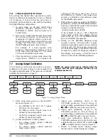
Page 38: ...ion Solution EA D A D physical error Call Rice Lake Weighing Systems RLWS Service EEEROM EEPROM physical error EVIREE Virgin EEPROM Use TEST menu to perform DEFLT restore defaults procedure then recalibrate load cells EPCKSM Parameter checksum error EACKSM A D calibration checksum error A D converter requires recalibration Call RLWS Service EFCKSM Printer format checksum error Call RLWS Service EL...

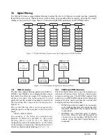
Page 39: ...the sum of the values representing the active annunciators For example if the annunciator status value returned on the ZZ command is 8224 the gross and standstill annunciators are lit 8224 represents the sum of the values for the standstill annunciator 8192 and the G gross mode annunciator 32 7 3 Continuous Output Stream Format Figure 7 1 shows the continuous output format sent to the IQ plus 350 ...

Page 40: ... 68 44 d 100 64 Ctrl E ENQ 05 05 37 25 E 69 45 e 101 65 Ctrl F ACK 06 06 38 26 F 70 46 f 102 66 Ctrl G BEL 07 07 39 27 G 71 47 g 103 67 Ctrl H BS 08 08 40 28 H 72 48 h 104 68 Ctrl I HT 09 09 41 29 I 73 49 i 105 69 Ctrl J LF 10 0A 42 2A J 74 4A j 106 6A Ctrl K VT 11 0B 43 2B K 75 4B k 107 6B Ctrl L FF 12 0C 44 2C L 76 4C l 108 6C Ctrl M CR 13 0D 45 2D M 77 4D m 109 6D Ctrl N SO 14 0E 46 2E N 78 4E ...

Page 41: ...AA 202 CA Ω 234 EA ï 139 8B 1 2 171 AB 203 CB δ 235 EB î 140 8C 1 4 172 AC 204 CC 236 EC ì 141 8D 173 AD 205 CD φ 237 ED Ä 142 8E 174 AE 206 CE 238 EE Å 143 8F 175 AF 207 CF 239 EF É 144 90 176 B0 208 D0 240 F0 æ 145 91 177 B1 209 D1 241 F1 Æ 146 92 178 B2 210 D2 242 F2 ô 147 93 179 B3 211 D3 243 F3 ö 148 94 180 B4 212 D4 244 F4 ò 149 95 181 B5 213 D5 245 F5 û 150 96 182 B6 214 D6 246 F6 ù 151 97 ...

Page 42: ...pecified as primary or secondary units on the IQ plus 350 indicator For these or other unlisted units of weight specify NONE on the UNITS parameter NOTE Ensure that the secondary decimal point position is set appropriately for the scale capacity in the secondary units If the converted value requires more digits than are available the indicator will display an overflow message OVERFL For example if...

Page 43: ...verall filtering effect is 256 4 x 8 x 8 With this configuration each A D reading has a 1 in 256 effect on the displayed weight value Setting the filters to 1 effectively disables digital filtering 1 x 1 x 1 1 7 6 2 DFSENS and DFTHRH Parameters The three digital filters can be used by themselves to eliminate vibration effects but heavy filtering also increases settling time The DFSENS digital filt...

Page 44: ...ion frequencies will cause more consecutive out of band readings so DFSENS should be set higher to counter low frequency transients Reconfigure as necessary to find the lowest effective value for the DFSENS parameter 7 7 Analog Output Calibration The following calibration procedure requires a multimeter to measure voltage or current output from the analog output module If the option is not already...

Page 45: ... first test menu function A DTST A D calibration functions ADOFFS and ADGAIN must be used only by qualified service personnel and only after replacing A D converter components Improper A D calibration may render the indicator unusable Figure 7 5 shows the Test Menu structure Figure 7 6 shows the front panel key functions in test mode Note that because the Test Menu functions are all on a single me...

Page 46: ...tus of DIGIN1 DI1 HI or DI1 LO D I 2 Display digital input 2 Press and hold Enter key to show status of DIGIN2 DI2 HI or DI2 LO AOUT 0 Set analog output to zero Press and hold Enter key to set analog output to its zero value AOUTFS Set analog output to full scale Press and hold Enter key to set analog output to its full scale value DEFLT Default parameters Press setup switch and Enter key at the s...

Page 47: ...gnal excitation and sense lines protected by capacitor bypass Analog Output Optional fully isolated voltage or current output 14 bit resolution Voltage output 0 10 VDC Load resistance 1kΩ minimum Current output 4 20 mA External loop resistance 500Ω maximum Digital Specifications Microcomputer Hitachi H8 3834 main processor 9 8304 MHz Digital Inputs 2 inputs TTL or switch closure active low Digital...

Page 48: ... not caused by accident misuse neglect alteration improper installation improper repair or improper testing RLWS shall be the sole judge of all alleged non conformities Such equipment has not been modified altered or changed by any person other than RLWS or its duly authorized repair agents RLWS will have a reasonable time to repair or replace the defective equipment Buyer is responsible for shipp...

Reviews: