background image

Rev 4, B0674R / B0664J, March 2014


Ishida Uni-7 & Uni-5 Series 

Setup Manual


Summary of Contents for Ishida Uni-5 Series

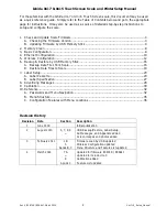
Page 1: ...Rev 4 B0674R B0664J March 2014 Ishida Uni 7 Uni 5 Series Setup Manual...

Page 2: ...5 Wireless Configuration 12 6 Backup Restore by USB Memory Stick 16 A Backup Data Files from Scale 16 B Restore Data Files to Scale 19 7 Label Setup 20 A Label Cassette 20 B Label Specification 27 8...

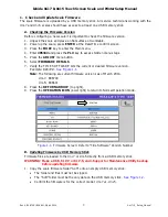
Page 3: ...menu button 6 Select FIRMWARE DETAILS 7 Verify the TITLE SOFTWARE lists the current or desired firmware version Example B0674R See Figure 1 1 Note The following are current firmware versions as of Mar...

Page 4: ...tion 4 Power up the scale and press the green ENTER button at the Date Time confirm screen Note Power up may take several minutes depending on the firmware version 5 The upper display bar will be red...

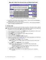
Page 5: ...l down and select DOWNLOAD page 2 3 11 At the DOWNLOAD MAIN screen press the MAIN ALL CLR button and press EXECUTE See Figure 1 5 Figure 1 5 Select and Execute MAIN ALL CLEAR 12 A warning message Data...

Page 6: ...34 0000 DATABASE VERSION IS DIFFERENT may be displayed Press EXEC to continue 19 Press EXEC to begin the firmware download See Figure 1 7 Figure 1 7 Press EXEC to Begin Firmware Download 20 The screen...

Page 7: ...mplete 22 Remove the USB Memory Stick 23 Wait five seconds and power up the scale 24 Press ENTER at the Date Time confirm screen 25 A warning message Data Composition Is Different Please Initialize th...

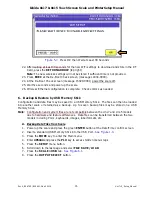
Page 8: ...p the scale and press the green ENTER button at the Date Time confirm screen 2 Press the MODE key to enter the Main menu 3 Enter 495344 and press the PLU key to access hidden menu steps 4 Press the AD...

Page 9: ...etc 3 Basic Configuration After loading new firmware the Uni 7 and Uni 5 scales default to a European format This is seen on the main display where the weight units are kg and the decimal points are...

Page 10: ...eless Configuration to complete communications setup of wireless scales Note If the scale will be hardwired to the network disconnect the patch cable from the internal bridge connected to the scale s...

Page 11: ...access point or another scale that will respond to a ping request 11 Set the COM CHECK PERIOD 600 10 minutes Note If the Com Check Period is set to zero the on line indicator on the main operation sc...

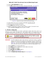
Page 12: ...option is not installed refer to the installation instructions document and install the bridge before configuring the wireless settings IMPORTANT The WiFi settings are stored in the RF Card Clearing t...

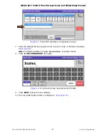
Page 13: ...onfiguration Screen 7 Enter the Network Name assigned to the Access Point s or Wireless Router s See Figure 5 2 Note The Network Name is always case sensitive Example Scales 8 Press the RETURN ARROW t...

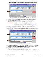
Page 14: ...If wireless comms must be disabled remove the patch cable plugged into the scale s LAN port See Figure 1 3 12 Select the appropriate encryption KEY TYPE HEX ASCII or PassPhrase See Figure 5 4 13 For...

Page 15: ...8 63 characters o HEX 8 31 characters Figure 5 5 Enter the Appropriate Encryption Key 16 Press the RETURN ARROW top right 17 Press SAVE to save the new settings 18 Wireless settings are now complete...

Page 16: ...ion and data files may be saved to a USB Memory Stick The files can then be loaded into another scale or retained as a backup Up to seven backup files may be stored on a USB Memory Stick Note Configur...

Page 17: ...utton to name the file See Figure 6 2 11 Enter a short name to describe the file Including the date is useful 12 Press RETURN ARROW top right to exit and save the file name See Figure 6 2 Figure 6 2 C...

Page 18: ...y Stick Compete Confirmation 17 Press RETURN ARROW top right to exit 18 Press the OPERATION ICON lower right to return to Normal Operation mode 19 Remove the USB Memory Stick When transferring the USB...

Page 19: ...SETUP menu button 6 Scroll down to the last page and select FILE SAVE LOAD 7 Press the USB SCALE tab See Figure 6 5 8 Press the green INPUT SELECT button Depending on the size of the files it may tak...

Page 20: ...wer right to return to Normal Operation mode 17 Remove the USB Memory Stick 7 Label Setup Labels are configured primarily in the Cassette menu Any special parameters if required are set in the Label S...

Page 21: ...ition 66x145mm 7 If the label requires special settings enter the LABEL SPEC value Note See section B Label Specification below for details 8 Set the PEEL MODE as needed Toggle between two selections...

Page 22: ...eld titles on the label ex Total Price Sell By etc default DISABLE do not print field titles on the label label titles are pre printed Figure 7 3 Label Cassette Setup Store Print and Title Print 15 Pr...

Page 23: ...eration default WITH OPERATOR operator tracking operator keys required to print CR SUBTOTAL ONLY cash register mode subtotal label for every transaction CR FIXED cash register mode single operator SEL...

Page 24: ...labels where the Extra Message 1 field will vary in length 26 Set the EXTRA MESSAGE 2 as needed Toggle between two selections FIXED select for die cut labels default VARIABLE select for continuous la...

Page 25: ...Press the button to move to the next page See Figure 7 9 31 Set the LOGO IMAGE 1 as needed Toggle between two selections FIXED select when Logo Image 1 will print on every label default VARIABLE sele...

Page 26: ...Image 3 Type and Height of Safe Handling Image 36 Press the button to move to the next page See Figure 7 11 37 Enter the HEIGHT OF LOGO IMAGE 1 as needed and press the Height of Image 1 field This is...

Page 27: ...menu 2 Enter 495344 and press the PLU key to access hidden menu steps 3 Press the SETUP menu button 4 Scroll down and select LABEL SPEC page 3 6 5 The current Label Specification settings are display...

Page 28: ...e 8 1 Ad Message Text and Settings 7 Enter the message text as needed 60 characters are available for scrolling messages 18 characters are available for flashing messages 8 Press the RETURN ARROW top...

Page 29: ...e Note Set the Display Count high enough to ensure all images are displayed 17 Press the RETURN ARROW top right 18 Repeat from step 4 to add more Advertising Messages 19 After entering all messages pr...

Page 30: ...needed to reset 6 To set the scale Range enter 495344 and press SINGLE or MULTI as needed For a 30 Lb scale Single will fix the resolution at 0 01 Lb from zero to full capacity 7 To select 60 Lb capac...

Page 31: ...stic rectangular cover and the seal bolt and metal cover See Figure 9 4 Figure 9 4 Calibration Access 13 Seal the scale as required by local regulations a Place a tamper evident decal over the Calibra...

Page 32: ...page menu steps are available Passwords 1 From the Operation screen press the MODE key to enter the Main menu 2 Enter the password followed by the PLU key Service password 495344 provides full access...

Page 33: ...on 1 Select the desired menu on the left side of the screen Example PROGRAM SETUP or ADJUST See Figure 10 2 Note The border color denotes the selected menu Figure 10 2 Uni 7 Main Menu 2 Use and button...

Page 34: ...n menu steps with multiple pages See Figure 10 4 Example select SETUP menu Select MACHINE No COMMS Four pages are available Access each page by pressing the desired tab 6 Press the RETURN ARROW top ri...

Page 35: ...OKING TIME PLU UPDATE DOWNLOAD NOTES Colored boxes indicate hidden menu steps Access by 495344 and PLU key from the main menu NUTRITION RECEIPT SETTING OPTION CHECK P3 EXTRA MSG 1 P3 CASSETTE P3 DISPL...

Page 36: ...Setup Label Format Language Setup Country MAC Address Setup MachineNo Comms IP Addr use for RF MAC Address filtering Maximum Tare Setup Country 495344 PLU Detail Weight 14789632 PLU Min Print Weight...

Reviews: