background image

Summit 3000 Low-Profile Floor Scale

14

Visit our website 

www.RiceLake.com

5.0

Specifications

End Load Capacity:

100% full scale at 2,000 lb and 5,000 lb
80% full scale at 10,000 lb

Load Cell Excitation

Rated Excitation: 10 VDC
Maximum Excitation: 15 VDC

Cable Length: 

20 ft (6.1 m) (for connecting junction box to indicator

Warranty:

Summit 3000 weldment and load cells two years, all other components one year

Approvals

   NTEP CC 92-001A9, Class III 5,000 d

Measurement Canada AM-5530, Class III 5,000 d

Summary of Contents for Summit 3000

Page 1: ...Summit 3000 Low Profile Floor Scale Installation Manual PN 76012 Rev C May 25 2021 ...

Page 2: ...emarks of their respective companies All information contained within this publication is to the best of our knowledge complete and accurate at the time of publication Rice Lake Weighing Systems reserves the right to make changes to the technology features specifications and design of the equipment without notice The most current version of this publication software firmware and all other product ...

Page 3: ...Safety 2 2 0 Installation 3 2 1 Scale Location 3 2 2 Unpack Scale 3 2 3 Adjust feet 4 2 4 Anchor Plate Installation 4 2 5 Electrical Connections 5 2 5 1 Electrical Grounding 5 2 5 2 Electrical Interface to Indicator 5 2 6 Pit Frame Concrete Details 7 2 7 Access Ramps 8 3 0 Adjustments and Calibration 9 3 1 Mechanical Adjustments 9 3 2 Corner Correction 9 3 3 Calibration Procedure 10 4 0 Maintenanc...

Page 4: ...00 Low Profile Floor Scale ii Visit our website www RiceLake com Rice Lake continually offers web based video training on a growing selection of product related topics at no cost Visit www ricelake com webinars ...

Page 5: ...ed in a durable ABS enclosure that has a convenient top access for future corner corrections Other available options include custom frames for pit installations and access ramps for all sizes Manuals are available for viewing and or downloading from the Rice Lake Weighing Systems website at www ricelake com manuals Warranty information can be found on the website at www ricelake com warranties 1 1...

Page 6: ... this manual has been read and all instructions are understood Failure to follow the instructions or heed the warnings could result in injury or death Contact any Rice Lake Weighing Systems dealer for replacement manuals Failure to heed could result in serious injury or death Do not allow minors children or inexperienced persons to operate this unit Do not operate without all shields and guards in...

Page 7: ...ystems where the scale is connected to a 120V AC circuit the instrument must be directly connected to an earth ground with a ground interface cable of no more than 3 resistance throughout its length 2 2 Unpack Scale Remove all packing material and inspect scale for visible damage caused during shipment Report any damage to the shipping company and Rice Lake Weighing Systems immediately Figure 2 1 ...

Page 8: ...are available for permanent applications and should be secured to the floor to prevent sideways movement of the scale 1 Using proper lifting technique Figure 2 1 on page 3 lift the scale so the feet are approximately one inch off the floor 2 Slide mounting plates under two feet diagonal from each other 3 Lower the scale back to the floor and position the plates so that the boltdown holes are acces...

Page 9: ...access plate located on the top of the scale Use the following steps to wire the junction box 1 Remove the access plate 2 Remove the four screws using an Allen wrench 3 Lift the junction box assembly out of the scale deck 4 Remove the top of junction box Figure 2 4 Junction Box Opened 5 Push the cable end into the junction box through a cord grip 6 Connect the wires to the indicator terminal Figur...

Page 10: ...ssary trim corners as described in Section 2 2 on page 3 11 Check all strain relief fittings for tightness 12 Put the cover back onto the junction box assembly and place the junction box back into the floor scale cutout 13 Secure the Summit 3000 floor plate Potentiometer Locations PT4 PT3 PT1 1 EXP PT2 1 CELL4 1 CELL1 1 CELL3 1 CELL2 1 IND EX SI SHD SI EX M T I O T A X C 100 SI 100 S2C I R N I T I...

Page 11: ... 92 59 92 71 92 83 92 71 92 F 47 92 59 92 59 92 59 92 71 92 Table 2 2 Drawing Dimensions Use concrete of minimum yield strength 5 000 PSI or six bag mix Allow seven days to cure wet concrete periodically during this time Dimensions shown assume firm stable soil conditions When soil conditions are not adequate place foundation at sufficient depth In wet or washdown applications it is recommended to...

Page 12: ...ure 2 6 Section Showing Installed Summit 3000 and Pit Frame 2 7 Access Ramps Access ramps for Summit 3000 floor scales are designed to bolt to the floor with built in mounting plates that attach to the scale feet When used with access ramps side movement of the scale is automatically eliminated and no other mounting plates are necessary Access ramps can only be oriented on the two scale sides that...

Page 13: ...ss known as trimming 1 Remove the junction box cover and identify the correct load cell terminal corresponding to each corner labeled CELL 1 CELL 2 CELL 3 and CELL 4 See Figure 4 3 on page 13 for scale deck corner numbering The indicator must be connected and calibrated but it does not need to indicate the exact weight value A test weight is required The recommended test weight for all Summit 3000...

Page 14: ...erything is seated 1 Load the scale to near capacity two or three times 2 With no load on the scale place the indicator in its calibration mode and perform a zero calibration 3 Place test weights on the platform equal to 70 100 of the scale s capacity If several weights are used they should be evenly distributed around the platform 4 Perform a span calibration 5 Remove the test weights and check t...

Page 15: ...y Power is disconnected Check power and reconnect Indicator fuse is blown Replace the fuse and check for the cause Interface cable is cut or disconnected Repair the cable Display stays at zero Indicator is faulty Service the indicator Load cell connections are faulty Check the cable connections in the junction box and at indicator Erratic weight readings Vibration is near scale Remove source of vi...

Page 16: ...cessary 4 Position load cells with alignment arrows pointed up toward the deck 5 Loosely install the hex head cap screws provided as shown in Figure 4 1 If the base is used with a pit frame or access ramp position the load cell to maintain the dimension shown in Figure 4 2 6 With the torque wrench tighten all bolts to 75 ft lbs Figure 4 2 Foot Pad Side View 7 Route the load cell cables near each c...

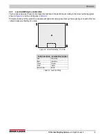
Page 17: ...ng system shown in Figure 4 3 and the coloring code in Table 4 2 Pull excess cable out of the junction box enclosure and tighten the cable grips until snug Finally gently pull on each of the four cables to make sure that they do not slip Figure 4 3 Corner Numbering Top View Cable Color Code Junction Box Terminal Red Excitation Black Excitation Green Signal White Signal Bare or Clear Shield Table 4...

Page 18: ...000 lb 80 full scale at 10 000 lb Load Cell Excitation Rated Excitation 10 VDC Maximum Excitation 15 VDC Cable Length 20 ft 6 1 m for connecting junction box to indicator Warranty Summit 3000 weldment and load cells two years all other components one year Approvals NTEP CC 92 001A9 Class III 5 000 d Measurement Canada AM 5530 Class III 5 000 d ...

Page 19: ......

Page 20: ... Canada Mexico 800 321 6703 International 715 234 9171 Europe 31 0 26 472 1319 Rice Lake Weighing Systems is an ISO 9001 registered company Rice Lake Weighing Systems Specifications subject to change without notice www ricelake com May 25 2021 PN 76012 Rev C ...

Reviews: