Connecting Electronic Equipment
© Rice Lake Weighing Systems
●
All Rights Reserved
21
7.0
Connecting Electronic Equipment
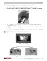
60' of six-wire homerun cable is supplied for wiring the junction box to the indicator. It is to be run in 3/4'' galvanized metal or
plastic conduit from the junction box to the indicator. Conduit for this purpose is to be obtained locally. A section of flexible
conduit with connector is provided where this cable exits the junction box. Do not run any other electrical cables in or near the
conduit to the indicator.
7.1 Indicator to Peripherals
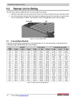
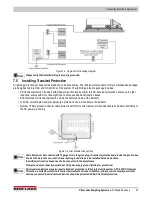
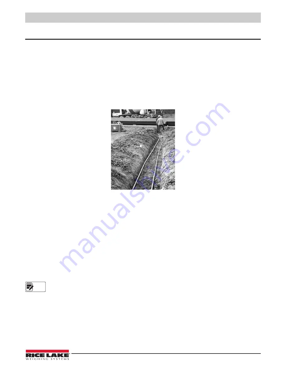
All conduit for cabling from the indicator to remote displays and other peripheral devices is to be obtained locally. Conduit runs
may be buried in a trench or secured above ground. Use separate conduit runs for AC power and DC data lines to avoid
interference. As a general guideline, run AC and DC cables in separate trenches if possible. When DC data cables must run in
the same trench as AC power lines, separate cables as much as possible.
Figure 7-1. Conduit Run in Trench
7.2 Single-Point Ground Conductor
A bare 10 gauge solid wire is run from the scale frame to the main AC power earth ground. DC transient protection must be
properly grounded to function correctly.
7.3 Junction Box Connections
Each junction box contains a JB8SPT summing board with DC transient protection devices. A desiccant such as the RLWS
Industrial Corrosion Inhibitor (PN 16037) should be added to the junction box enclosure before final closure.
In a truck scale up to 70' long, a single junction box is located in a junction box pocket in the center or
B
module (
). A summing card mounted within the junction box is used to make all cable terminal connections. All terminal pins are
clearly marked as to function.
On scales over 70' long with four or more modules, two or more junction boxes are necessary.
Refer to assembly print or foundation plan for junction box location and homerun cable output.
Note

