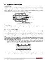
Set Load Cell Mounts
9
4.5
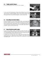
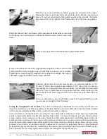
Tighten Load Cell Screws
Turn in and tighten both load cell screws to 50 ft.lb. minimum.
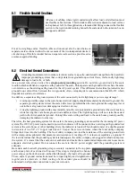
You can now tell if the baseplate is directly under the chair by how the top
convex surface of the link is aligning with the concave bearing surface of the
chair. If necessary, slide the baseplate sideways to improve the alignment. The
final alignment will be done when the baseplate is raised in the next step.
4.6
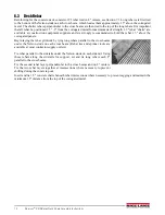
Raise Mount into Final Position
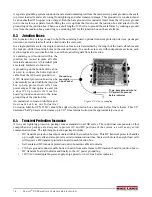
Turn the leveling screws to raise the mount until the link is centered in the chair
bearing and lightly touching. Level the plate in both directions.When the
baseplate is directly under the chair, the link will be hanging exactly vertical
when centered in the chair. Approximately 1/4" of link should protrude beyond
each side of the chair. If adjustment is necessary, tap baseplate edges lightly with
a hammer to slide the entire mount sideways.
4.7
Attach Flexible Conduit Sections
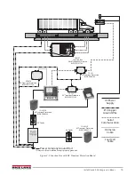
A 30" section of flexible conduit is included for each load cell. One end is
threaded for mating with the LB connector at the load cell. The other end adapts
to 3/4" galvanized rigid conduit. Thread the load cell cable through the flexible
section and turn the threaded end into the LB connector.
To maintain level of scale deck, don’t remove shims and blocks beneath siderails
until all mounts are set. When all are set, jack siderails at each mount location
just enough to remove shims and blocks. Gently lower the siderail onto the load
cell at each mount.
1/4
"
Summary of Contents for Survivor SR
Page 1: ...SURVIVOR SR Siderail Truck Scale Assembly Instructions 45698 Rev D...
Page 2: ......
Page 29: ......

