- -
7
G-5. Set the power switch to the ON position, the indicator
lights may blink and the internal alarm may sound
momentarily. This is normal.
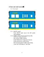
G-6. Check the meters and indicators on the front panel of
the inverter. The voltage bar graph indicate
depending on the voltage of the power source.
If it does not, check your power source and the
connections to the inverter. The other indicators
should be off. Plug the test load into the AC
receptacle on the front panel of the inverter. Leave
the test load switch off.
G-7. Set power inverter switch to the ON position and turn
the test load on, the inverter should supply power to
the load. If you plan to measure the true output r.m.s.
Voltage of inverter, the meter such as FLUKE 45
BACKMAN 4410 or TRIPLETT 4200 or other digital
meters must be used.
H. Installation:
H-1. Where to install
The power inverter should be installed in location that
meets the following requirements:
H-1-1. Dry
Do not allow water to drip or splash on the inverter.
WARNING!
Reverse polarity connection will blow a fuse in
Inverter and may permanently damage the inverter.
Damage caused by reverse polarity connection is
not covered by our warranty.


