background image

RP-II-CS8G [C]

18

Sheet 2 of 16

 www.richards-mfg.com

Product Family

CS8

WARNING

•  System must be de-energized during installation or future operation of this product or its components.
•  Do not touch or move energized connectors or components by hand.
•  Excess distortion of the assembled connector may result in its failure.
•  Failure to follow these instructions will result in damage to the connector and serious or fatal injury.
•  This product should only be installed and/or operated by trained personnel in accordance with normal and safe work procedures.
•  Variations in equipment or configuration or work procedures may not be covered in these instructions.
•  Please contact Richards Manufacturing for any additional questions.

 Guidelines for Installation in Cold Temperatures (<32 degrees F):

•  The cold shrink product must be kept and stored in a clean, dry manner.  These high voltage cable accessories have internal phase to ground insulating 

interfaces which must be intact.

•  Keep product within a warmer climate controlled environment as long as possible PRIOR to installation.  This may be the cab of an operating vehicle if 

no other facility resources are available.

•  If product has been inadvertently exposed and stored in freezing (or below) temperatures for an extended or unknown period of time:  Product must 

warmed (41F or greater) and inspected prior to installation.

•  If installing product in temperatures below freezing, and conducting post installation electrical testing – it may be necessary to warm the cable interface 

of the accessory.  This can increase the contact pressure between the cable accessory and the cable substrate.  The heat should be applied primarily 
around the cable semicon shield cutback area.  This can be accomplished via a space heater or  hot air gun.  The cable accessory should be gently heated 
so that the product becomes warm to the touch.  Heat should not be concentrated but should be applied circumferentially around the product.  If using a 
hot air gun, care must be taken not to apply the heat in a concentrated manner that could damage the cable or accessory.  Check that proper ventilation 
is available if working in a confined space structure.
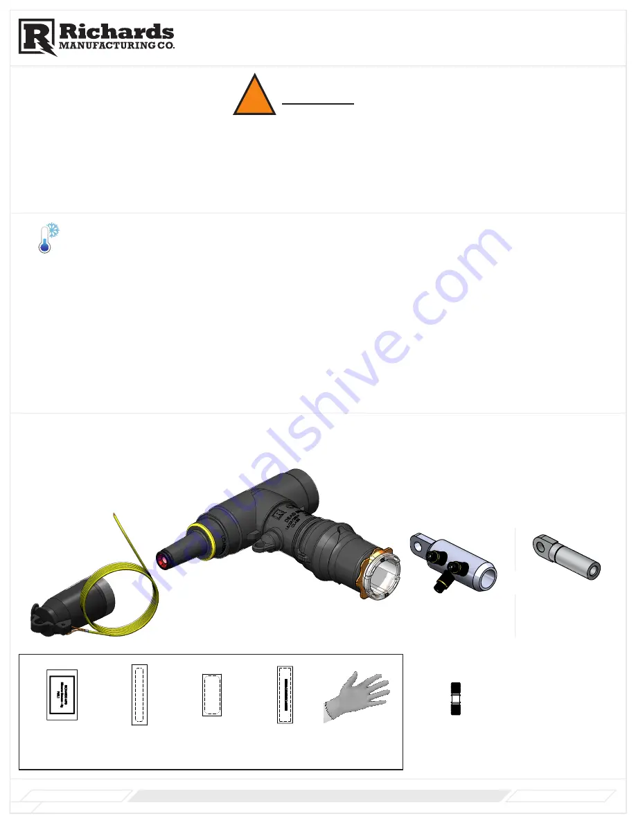
KIT CONTENTS

Standard kits may include the following. Custom kits may vary.

Check package contents to be sure they are complete, undamaged,and properly sized for the application.

!

A

A

B

B

C

C

D

D

E

E

F

F

G

G

H

H

J

J

K

K

L

L

M

M

N

N

P

P

R

R

T

T

24

24

23

23

22

22

21

21

20

20

19

19

18

18

17

17

16

16

15

15

14

14

13

13

12

12

11

11

10

10

9

9

8

8

7

7

6

6

5

5

4

4

3

3

2

2

1

1

DRAWN

CHK'D

APPV'D

MFG

Q.A

UNLESS OTHERWISE SPECIFIED:

DIMENSIONS ARE IN MILLIMETERS

SURFACE FINISH:

TOLERANCES:

   LINEAR:

   ANGULAR:

FINISH:

DEBURR AND 

BREAK SHARP 

EDGES

NAME

SIGNATURE

DATE

MATERIAL:

DO NOT SCALE DRAWING

REVISION

TITLE:

DWG NO.

SCALE:1:1

SHEET 1 OF 1

A0

As Noted

N/A

WEIGHT: 5.06

618FCN-01A

15 kV Cold Shrink 

R800; F Style;  

(EXPANDED) Test 

Point - Size P

G Style Cold Shrink R-800 (CS8)

(15kV or 25kV)

A

A

B

B

C

C

D

D

E

E

F

F

G

G

H

H

J

J

K

K

L

L

M

M

N

N

P

P

R

R

T

T

24

24

23

23

22

22

21

21

20

20

19

19

18

18

17

17

16

16

15

15

14

14

13

13

12

12

11

11

10

10

9

9

8

8

7

7

6

6

5

5

4

4

3

3

2

2

1

1

DRAWN

CHK'D

APPV'D

MFG

Q.A

UNLESS OTHERWISE SPECIFIED:

DIMENSIONS ARE IN MILLIMETERS

SURFACE FINISH:

TOLERANCES:

   LINEAR:

   ANGULAR:

FINISH:

DEBURR AND 

BREAK SHARP 

EDGES

NAME

SIGNATURE

DATE

MATERIAL:

DO NOT SCALE DRAWING

REVISION

TITLE:

DWG NO.

SCALE:1:2

SHEET 1 OF 1

A0

As Noted

N/A

WEIGHT: 1.14

21LBIC-01A

15kV 200A 

Loadbreak 

Insulating Cap 

with Green 

Insulated Ground 

Wire;

Insulating Cap

21LBICG (for 15kV Class)
22LBICG (for 25kV Class)

WARNING

KIT CONTENTS

Applicable Catalog Prefix

Product Family

CSHN/CSHT

Installation Instructions

WARNING

KIT CONTENTS

Applicable Catalog Prefix

Product Family

CSHN/CSHT

Installation Instructions

Shear Bolt Lug

P6ALR-X-

15

/

16

15

/

16

 Threaded Hole 

Lug

P6AL-X-

15

/

16

P7ALCU-X-

15

/

16

P9CU-X-

15

/

16

OR

(1) Cable Prep Pack containing:

Silicone Lubricant

P6SL1

Jacket Mastic

(1) Piece

Sealing Mastic

(1) Piece

Stress Control

Mastic

(1) Piece

Latex Gloves

(1) Pair


Stud

P625HIP-STUD
P925HIP-STUD

Summary of Contents for Cold Shrink R-800

Page 1: ...stallation Instructions CS8 Series Cold Shrink R 800 Applicable Fastener Type Applicable Housing Sizes G Style O P Q Applicable Catalog Prefix For Use With the Following Cable Types 15kV Class 25kV Class Jacketed Concentric Neutral JCN Longitudinally Corrugated Neutral LC Tape Shield Neutral 61CS8G 71CS8G 91CS8G 62CS8G 72CS8G 92CS8G 18 17 16 15 14 13 12 11 10 9 ...

Page 2: ...e between the cable accessory and the cable substrate The heat should be applied primarily around the cable semicon shield cutback area This can be accomplished via a space heater or hot air gun The cable accessory should be gently heated so that the product becomes warm to the touch Heat should not be concentrated but should be applied circumferentially around the product If using a hot air gun c...

Page 3: ...allation Instructions 1 1 2 REF 12 Cable Jacket Abraded Area A Straighten and train cable end Cable should be free to move approximately 2 in either direction B Cut cable to dimensions shown C Clean cable jacket approximately 24 from end of cable TIP Use to scale cable cutback template on last page as aid to prepare cable NOTE Certain items used such as mastic PVC tape shrink tube etc may not be i...

Page 4: ...own B STEP 5 Preparing Metallic Shield Remove cable insulation to dimension shown Confirm all dimensions with To Scale Cable Cutback Template on last page or Strap Wire Shielded Cable Go to Step 7 For Metallic Tape Shielded LC Shielded Remove semi conductive shield to dimension shown A WARNING Do not nick or cut the cable insulation WARNING Do not nick or cut the cable insulation STEP 4 Exposing C...

Page 5: ... cutback Apply the mastic with light tension so it slightly stretches and completely wraps the cable Wipe Direction A B C D E F G H J K L M N P R 12 11 10 9 8 7 6 5 4 3 2 1 DRAWN CHK D APPV D MFG Q A UNLESS OTHERWISE SPECIFIED DIMENSIONS ARE IN MILLIMETERS SURFACE FINISH TOLERANCES LINEAR ANGULAR FINISH DEBURR AND BREAK SHARP EDGES NAME SIGNATURE DATE MATERIAL DO NOT SCALE DRAWING REVISION TITLE D...

Page 6: ...8 18 17 17 16 16 15 15 14 14 13 13 12 12 11 11 10 10 9 9 8 8 7 7 6 6 5 5 4 4 3 3 2 2 1 1 DRAWN CHK D APPV D MFG Q A UNLESS OTHERWISE SPECIFIED DIMENSIONS ARE IN MILLIMETERS SURFACE FINISH TOLERANCES LINEAR ANGULAR FINISH DEBURR AND BREAK SHARP EDGES NAME SIGNATURE DATE MATERIAL DO NOT SCALE DRAWING REVISION TITLE DWG NO SCALE 1 1 SHEET 1 OF 1 A0 As Noted N A WEIGHT 5 06 618FCN 01A 15 kV Cold Shrin...

Page 7: ...NING Fastener is factory installed in a retracted position The Fastener must be stroked into forward position The female threaded end of Fastener will then extend into the 15 16 Threaded hole of the Lug WARNING Confirm that fastener goes through lug hole as shown below Fastener in the retracted position Fastener Lug Hex Tool Push Fastener stroked into forward position through Lug Hole Fastener thr...

Page 8: ...ther push CS8 onto mating part lining up the hole in the lug with the stud on the mating part D Insert Hex tool P620AT or equivalent 5 16 hex tool into loadbreak interface and engage faster Rotate tool 2 3 turns to start thread engagement CHECK Tug on power cable to confirm stud is through hole in lug Only a small amount of movement should be possible If the cable moves more than a small amount re...

Page 9: ...core into two halves and clip any plastic rings that remain on cable Removal Ring A B C D 10 2 Preparing Metallic Shield For Metallic Tape LC Shielded A Install jacket mastic on cable jacket aligned with jacket cutback B Wrap tinned copper braid around exposed metallic shield C Align edge of solder block with jacket cutback D Secure copper braid 3 back from end of jacket mastic with zip tie or bin...

Page 10: ...ing Mastic Jacket Mastic completely covered with Sealing Mastic Jacket Mastic completely covered with Sealing Mastic 12 Applying Jacket Seal For Strap Wire Shielded Cable A Apply grease over area as shown Only use grease supplied with kit or approved silicone grease B Hold both tabs and pull out to completely cover sealing mastics as shown below Ensure sealing mastic is not dislodged when unfoldin...

Page 11: ...ed or approved silicone grease loadbreak interface of CS8 and interface of insulating cap or mating part B Install mating component per manufacturer instructions Loadbreak Cap shown as reference Wires adbreak Interface STEP 17 Connecting R800 to Ground R80 Installation Instructions Clean and Lubricate Internal Cavity Clean and Lubricate ...

Page 12: ...onnect other end of wire to copper braid C Ground the cable shield according to appropriate approved practice For Strap Wire Shielded Cable A Insert one end of a piece of wire 14 AWG copper or larger through one of the available grounding eyes and twist to make a small loop Be sure not to damage grounding eye B Connect other end of wire to shield wires C Ground the cable shield according to approp...

Page 13: ...RP II CS8G C 18 Sheet 13 of 16 www richards mfg com Product Family CS8 ...

Page 14: ...e Insulation Conductor Conductor intentionally not shown exposed Multiple insulation cutback lengths exist depending on lug being installed Locate appropriate dimension within instructions dimension should not exceed 4 3 8 11 9 3 4 8 3 4 10 11 3 4 To Scale Cutback Template Provided by the factory ...

Page 15: ...RP II CS8G C 18 Sheet 15 of 16 www richards mfg com Metallic Shield Jacket Semi Conductive Shield To Scale Cutback Template Provided by the factory ...

Page 16: ...RP II CS8G C 18 Sheet 16 of 16 www richards mfg com Product Family CS8 ...

Reviews: