


RP-II-CS8G [C]
18
Sheet 4 of 16
www.richards-mfg.com
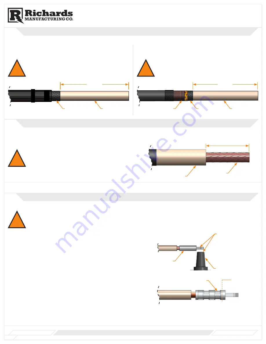
Product Family
CS8
4
Exposing Cable Insulation
For Strap/Wire Shielded Cable
A. Remove semi-conductive shield to dimension shown.
For Metallic Tape/LC Shielded Cable
A. Remove semi-conductive shield to dimension shown.
!
WARNING: Do not nick or cut the cable insulation.
!
WARNING: Do not nick or cut the cable insulation.
Copper Braid
Around Tape Shield
Solder Block
Cable Jacket
Metallic Tape Shield
Sealing Mastic
4 38 "
Cable Insulation
Cable Conductor
Lug
Locate first crimp on
this end
7
1
8
MAX
Securing
PVC Tape
PVC Tape
Constant Force
Spring
Tape Marker
Wrap constant force spring over wrapped portion of copper braid.
C.
Wrap 2 layers of PVC tape over constant force spring.
D.
Press solder block into jacket mastic.
E.
Secure braid to cable with PVC Tape.
F.
For Metallic Tape Shield/LC Shielded
Position copper braid so that solder block rests on the jacket mastic.
A.
Wrap copper braid around metallic tape shield as shown.
B.
STEP 5-Preparing Metallic
Shield
Remove cable insulation to dimension shown.
A.
NOTE:
Confirm all dimensions with To-Scale Cable Cutback Template on last page
before proceeding.
WARNING: Do not nick or cut conductor strands.
For Strap/Wire Shielded Cable
Go to Step 7
For Metallic Tape Shielded/LC Shielded
Remove semi-conductive shield to dimension shown.
A.
WARNING: Do not nick or cut the cable insulation.
WARNING: Do not nick or cut the cable insulation.
STEP 4-Exposing Cable
Insulation
For Strap/Wire Shielded Cable
Remove semi-conductive shield to dimension shown.
A.
Clean conductor from any debris. For aluminum conductor wire brush and
A.
immediately insert lug onto conductor.
Slide lug on to conductor until fully seated. Using approved tool/press and correct die
B.
per crimp chart, crimp lug starting from pad side. Rotate 90° for each crimp.
For aluminum and bi-metal lugs carefully wipe all excess inhibitor from lug and cable
C.
insulation after crimping.
NOTE:
If using a shearbolt lug, please reference the instructions conatined within the
shearbolt lug package.
CHECK:
Confirm lug dimension does not exceed dimension given.
STEP 6- Exposing the
Conductor
STEP 7- Installing Lug
Product Family
CSHN/CLCT
Installation Instructions
www.richards-mfg.com
RP-II-62CSHNT [A]
Rev. A
Sheet 9 of 9
517 Lyons Ave.
Irvington, NJ 07111
Phone (973) 371-1771
Fax (973) 371-4304
www.richards-mfg.com
Cable Insulation
9
3
/
4
”
Semi-Conductive
Shield
Copper Braid
Around Tape Shield
Solder Block
Cable Jacket
Metallic Tape Shield
Sealing Mastic
4 38 "
Cable Insulation
Cable Conductor
Lug
Locate first crimp on
this end
7
1
8
MAX
Securing
PVC Tape
PVC Tape
Constant Force
Spring
Tape Marker
Wrap constant force spring over wrapped portion of copper braid.
C.
Wrap 2 layers of PVC tape over constant force spring.
D.
Press solder block into jacket mastic.
E.
Secure braid to cable with PVC Tape.
F.
For Metallic Tape Shield/LC Shielded
Position copper braid so that solder block rests on the jacket mastic.
A.
Wrap copper braid around metallic tape shield as shown.
B.
STEP 5-Preparing Metallic
Shield
Remove cable insulation to dimension shown.
A.
NOTE:
Confirm all dimensions with To-Scale Cable Cutback Template on last page
before proceeding.
WARNING: Do not nick or cut conductor strands.
For Strap/Wire Shielded Cable
Go to Step 7
For Metallic Tape Shielded/LC Shielded
Remove semi-conductive shield to dimension shown.
A.
WARNING: Do not nick or cut the cable insulation.
WARNING: Do not nick or cut the cable insulation.
STEP 4-Exposing Cable
Insulation
For Strap/Wire Shielded Cable
Remove semi-conductive shield to dimension shown.
A.
Clean conductor from any debris. For aluminum conductor wire brush and
A.
immediately insert lug onto conductor.
Slide lug on to conductor until fully seated. Using approved tool/press and correct die
B.
per crimp chart, crimp lug starting from pad side. Rotate 90° for each crimp.
For aluminum and bi-metal lugs carefully wipe all excess inhibitor from lug and cable
C.
insulation after crimping.
NOTE:
If using a shearbolt lug, please reference the instructions conatined within the
shearbolt lug package.
CHECK:
Confirm lug dimension does not exceed dimension given.
STEP 6- Exposing the
Conductor
STEP 7- Installing Lug
Product Family
CSHN/CLCT
Installation Instructions
www.richards-mfg.com
RP-II-62CSHNT [A]
Rev. A
Sheet 9 of 9
517 Lyons Ave.
Irvington, NJ 07111
Phone (973) 371-1771
Fax (973) 371-4304
www.richards-mfg.com
9
1
/
4
”
Semi-Conductive
Shield
Cable Insulation
Metallic Shield
9
3
/
4
”
8
3
/
4
”
5
Exposing Conductor
A. Remove cable insulation. Refer to instructions provided with lug for
insulation cutback dimension. Cutback dimension should not exceed 4
3
/
8
".
Cable Conductor
Cable Insulation
Insulation Cutback
!
WARNING: Do not nick or cut the conductor strands.
NOTE:
Confirm all dimensions with To-Scale Cable Cutback Template before proceeding.
6
Installing Lug
!
WARNING: Lug MUST have a
15
/
16
” hole. Confirm lug and hole dimension before installing lug.
A. Clean conductor of any debris. For aluminum conductor, wire brush and
immediately insert lug onto conductor. Slide lug until the conductor is fully
seated within the lug barrel.
B. Rotate lug so that spade is parallel to the contact face of the bushing or
mating part as shown.
C.
For Shear Bolt Connectors:
Install lug using separate instructions
provided with lug.
For Crimp Connectors:
Select correct tool and die using crimp chart
supplied with lug. Crimp lug (min. number indicated in crimp chart)
starting just below knurl line adjacent to pad as shown. Carefully wipe
any excess inhibitor from lug and cable insulation.
A
A
B
B
C
C
D
D
E
E
F
F
G
G
H
H
J
J
K
K
L
L
M
M
N
N
P
P
R
R
T
T
24
24
23
23
22
22
21
21
20
20
19
19
18
18
17
17
16
16
15
15
14
14
13
13
12
12
11
11
10
10
9
9
8
8
7
7
6
6
5
5
4
4
3
3
2
2
1
1
DRAWN
CHK'D
APPV'D
MFG
Q.A
UNLESS OTHERWISE SPECIFIED:
DIMENSIONS ARE IN MILLIMETERS
SURFACE FINISH:
TOLERANCES:
LINEAR:
ANGULAR:
FINISH:
DEBURR AND
BREAK SHARP
EDGES
NAME
SIGNATURE
DATE
MATERIAL:
DO NOT SCALE DRAWING
REVISION
TITLE:
DWG NO.
SCALE:2:1
SHEET 1 OF 1
A0
Richards Black Epoxy A
WEIGHT:
AB Bushing
3" 15/25 kV 600 A
AB Bushing
A
A
B
B
C
C
D
D
E
E
F
F
G
G
H
H
J
J
K
K
L
L
M
M
N
N
P
P
R
R
T
T
24
24
23
23
22
22
21
21
20
20
19
19
18
18
17
17
16
16
15
15
14
14
13
13
12
12
11
11
10
10
9
9
8
8
7
7
6
6
5
5
4
4
3
3
2
2
1
1
DRAWN
CHK'D
APPV'D
MFG
Q.A
UNLESS OTHERWISE SPECIFIED:
DIMENSIONS ARE IN MILLIMETERS
SURFACE FINISH:
TOLERANCES:
LINEAR:
ANGULAR:
FINISH:
DEBURR AND
BREAK SHARP
EDGES
NAME
SIGNATURE
DATE
MATERIAL:
DO NOT SCALE DRAWING
REVISION
TITLE:
DWG NO.
SCALE:1:5
SHEET 1 OF 1
A0
As Noted
N/A
WEIGHT: 8.85
RP-II-63LCN Step 10
RP-II-63LCN Step
10
Bushing
Lug
Ensure surfaces
are parallel before
installing lug
Locate first
crimp here
Knurl Line


