北京锐志天宏科技股份有限公司
Beijing RichAuto S&T Co., Ltd.
33
Forging ahead, create future together!
(
,
,
,
,
,
)
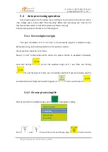
,the machine will move accordingly.
Note:
The movement will be carried out according to the current speed mode and the set
distance, it is not affect by the ‘grid’, so it will not stop on grid point. To change the distance value,
triple press “
” re-enter the ‘Distance’ value setting.
5.3.3
Manual testing input and output
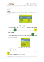
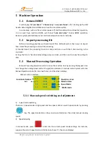
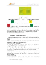
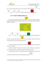
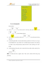
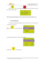
Under the initial boot interface, that is screen displays as follow,
Double press “
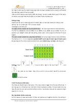
”, the screen, it will displays two rows of arrows which defaults all
arrows are downwards “↓”.
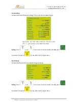
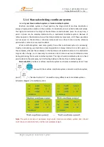
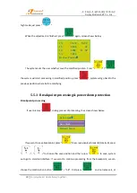
Upper arrows represent input signals: the former 4 numbers 0, 1, 2, 3
corresponding to X HOME, Y HOME, Z HOME and A HOME. The remaining 4 numbers respective
to tool setting, driver alarm, emergency stop and foot switch (cycle switch) input signals.
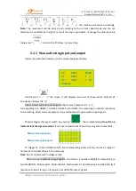
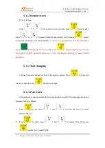
Manual trigger the signal switch by pressing “
”, the corresponding
arrow flip up
indicates that the signal is normal
. If not, user should check its switch, wiring and 50 pins cable.
To trigger X1 (X axis HOME switch), the corresponding arrow will flip, means X1 signal is
normal. X2 to X8 detecting is in the same way.
Note
: Do not confuse with “Voltage setup”.
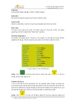
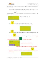
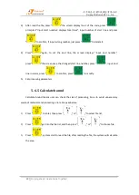
Down arrows represent output signals
:
the former 4 numbers
0
,
1
,
2
,
3
corresponding to
Spindle ON/OFF, Multi-speed 1, Multi-speed 2, Multi-speed 3; The remaining 4 numbers
4
,
5, 6, 7
respective to alarm lamp, run lamp and user definable output signals.
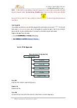
Manual test input ports
Manual test output ports
1 X 0.000
MAUN
1 Y
0.000
F 2
1 Z
0.000
L N1
Continue

