Beijing RichAuto S&T Co., Ltd.
51
2.
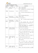
Parameter setting
Para.
No.
Function
Value
Description
*Pn000 Function
selection basic
switch 0
0010
Bit 0
:
Set 0,positive rotation at positive rotation
command
Bit 1
:
Set 1,position control mode(pulse sequence
command)
*Pn200 Format seletion
switch of
position control
command
0005
Bit 0
:
Set 5,select the instruction mode as
“pulse+direction”,negative logic
*Pn20E Electronic gear
ratio(numerator)
Need
calculation
Z1
=
Encoder pulse count per revolution×4;
Z2
=
Pulse equivalent×Screwpitch×Transmission
ratio
e.g. Pulse equivalent 1000
,
Screw pitch 10mm,
Encoder resolution 5000
,
Transmission ratio 1
Z1/Z2= 5000×4/1000×10×1=2/1
set Pn20E=2,set Pn210=1
.
The numerator and
denominator of electronic gear ratio is reducible to
set the value of Pn20E and Pn210 as a integer in the
range of 1~65536.
*Pn210 Electronic gear
ratio(denominato
r)
Need
calculation
*Pn50A Input signal
selection 1
8170
Bit 1
:
Set 7,servo on all the time.
Bit 3
:
Set 8,positive rotation not used and signal
input(P-OT)prohibited
*Pn50F Output signal
selection 2
0300
Set it when servo motor with brakes.
Bit 2
:
Set 3,brake interlock signal “/BK”is output
from CN1-29,CN1-30 to control 24V relay used for
brake
*Pn50E Output signal
selection 1
0211
Set it when servo motor with brakes.
To avoid of CN1-29 and CN1-30 being used for
other function and leading to brake ineffective,3 is
not allowed to appear in the 4 digits.
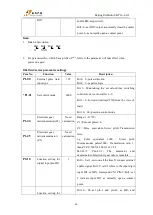
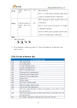
NOTE
:
1.
Data bit description:
…
Bit3 Bit2 Bit1 Bit0
…
X XXX
2. For parameters No. which has a prefix of "*", refers to the parameter will take effect when
power on again. If it has not connected the brake, then no need to set Pn50E and Pn50F.
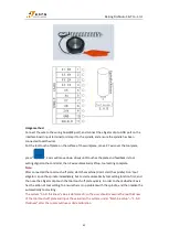
3. The servo alarm signal corresponds to the pin number ALM+
:
pin-31; ALM-
:
pin-32; Signal
type default normal close. The default alarm input terminal of B11, B12, B15 is on X5 port


