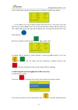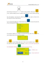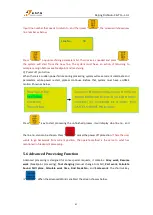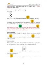
Beijing RichAuto S&T Co., Ltd.
53
2.
Parameter settings
Para.
No.
Function
Value
Description
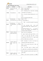
*Pr0.00
Settingthe direction
of rotation
0
If the motor rotation direction opposite to the
actual needs, set 1.
*Pr0.01
Select control mode
0
0:Position mode,1
:
velocity mode,2
:
torque mode
*Pr0.05
Selection
of
command pulse input
0
0:Photo-coupler input
(
PULS1,PULS2,SIGN1,SIGN2
)
1:Exclusive input for line driver
(
PULSH1,PULSH2,SIGNH1,SIGNH2)
*Pr0.07
Command pulse input
mode setup
3
Set
command
pulse
input
mode:commacommand
direction,
negative logic.
*Pr0.08
Command pulse No.
per motor circle
0
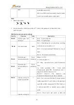
When it is set to “0”,parameters Pr0.09 and
Pr0.10 are valid
Pr0.09
1st numerator of
command pulse
frequency
multiplication
Need
calculatio
n
Range:0~
2
30
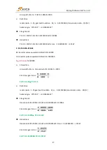
Z1
=
Encoder resolution
Z2
=
Pulse equivalent×Screwpitch×Transmission
ratio
e.g. Pulse equivalent 1000
,
Screw pitch 10mm,
Encoder resolution 10000
,
Transmission ratio 1
Z1/Z2= 10000/1000×10×1=1/1
set Pr0.09=1,set Pr0.10=1
.
The numerator and
denominator of electronic gear ratio is
reducibleto set the value of Pr0.09 and Pr0.10as
integer,range: 0~2
30
.
Pr0.10
Denominator of the
command pulse
frequency
multiplication
Need
calculatio
n
Range:0~
2
30
*Pr4.05
Function setting for
digital input pin SI6
8618883
Bit1,0:Set 83,servo on all the time.
Note:
1.
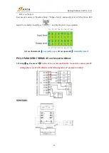
Data bit description:
…
Bit3 Bit2 Bit1 Bit0
…
X XXX
2. For parameters No. which has a prefix of "*", refers to the parameter will take effect when
power on again.
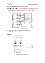
3. The servo alarm signal corresponds to the pin number ALM+
:
pin-37; ALM-
:
pin-36; Signal
type default normally closed.

