Beijing RichAuto S&T Co., Ltd.
60
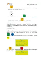
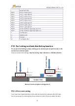
To confirm the contact position between the tool and the workpiece by eye-measurement or tool
bit touch the workpiece surface. Then press “Z
→
0” to finish the tool setting.
PS5.2 Fixed calibration
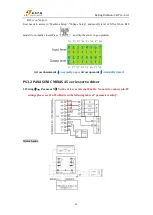
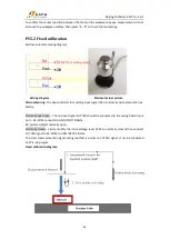
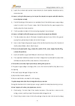
Microset electrical wiring diagram:
Wiring diagram
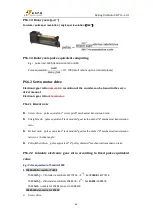
Microset actual picture
Microset wiring:
The dsp controller tool setting input signal (X4) is normally open state when ex-
factory.
Normally open type
:
The microset signal CUTTER should be connected to the wiring board input
port --X4, COM connects to GND-INPUT SIGNAL.
X4: system default normally open.
Normally closed
:
Firstly, modify the input voltage level of X4 to normally closed, then connect
CUTTER signal to X4, COM to GND-INPUT SIGNAL.
The Over travel protection signal wiring method is similar to CUTTER signal. It can be connected
to X7-E-stop signal.
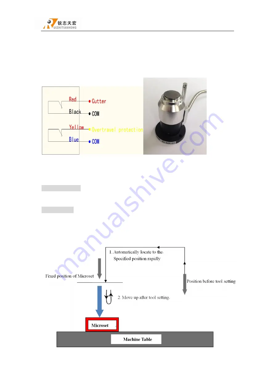
Fixed calibration diagram:
(Tool setting signal)

