background image

GTR099 swing gate opener manual – Revision 22 

19


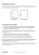
Connecting wires using screw-type terminals: 

To connect to any of the screw type terminals on the circuit board, you will need to firmly pull the green terminal 
off the circuit board and use a small screwdriver to loosen the screw. Make sure the wire is cleanly twisted, and 
there are no frayed wires sticking out. Feed the wire into the required terminal, ensuring full contact with the 
metal. Retighten the screws, and then tug on the wire to ensure that it is securely fastened. Once all wires are 
inserted and fastened, push the green terminal back into the circuit board, making sure it clicks in and is sitting 
flush. Lastly, check that the wires are not contacting a neighbouring terminal as this can cause a short circuit. 

1. Actuator


Insert the stripped cable wires into the appropriate terminals on the opener terminals block. The red wire should 
be inserted into the “+MOTOR” terminal (#17), the black wire into “MOTOR-” terminal (#18), the blue wire into 
“DLMT” terminal (#19), the green wire into “COM” terminal (#20), and the yellow wire into “ULMT” terminal (#21). 

2. Battery (optional)


The “24V+” of the battery should be wired to the +BAT (#11) terminal, “24V-” should be wired to “BAT-” (#12) 
terminal.


3. AC Power Adaptor


Insert the stripped cable wires into DC24V (#13&#14) terminals to the control board. No matter the polarity.


4. Alarm Lamp (optional) 

The red wire of the alarm lamp should be inserted into either LAMP (#15) terminal, the white wire into the other 
one (#16).


5. Photocell Beam System (PBS) (optional) 

Please refer to your accessories manual for correct connection


6. Push Button (optional)


The push button should be wired to the “#4 and “#5” terminals. No matter the polarity. The gate operator works 
alternately by pressing the button (open-stop-close-stop-open).


7. Electric Lock (optional)


Please refer to your accessory manual for correct connection 

8. Exit Wand (optional)


Please refer to your accessory manual for correct connection 

9. Wired Keypad (optional)


Please refer to your accessory manual for correct connection 


10. External Receiver (optional)


Please refer to your accessory manual for correct connection 


Summary of Contents for GTR099

Page 1: ...se read and follow all warnings precautions and instructions before installation and use 2 x 12V 7Ah batteries are supplied The AC adaptor included is used to maintain charge in the batteries Periodic...

Page 2: ...echnical Specifications Features 6 Installation Overview 9 Preparation for Installation 9 Install the Gate Opener on the Gate 10 Mounting of the control box 16 Connection of the power supply 16 Connec...

Page 3: ...ar gate 8 Pedestrians should never cross the pathway of a moving gate The gate opener is not acceptable for use on any pedestrian gate Pedestrians must be supplied with a separate pedestrian access 9...

Page 4: ...GTR099 swing gate opener manual Revision 22 4 Parts List...

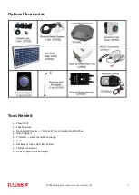
Page 5: ...tional Accessories Tools Needed Power Drill Tape Measure Open End Wrenches 14mm 17mm or Adjustable Wrenches Wire Strippers C Clamps small medium and large Level Hacksaw or Heavy Duty Bolt Cutters Phil...

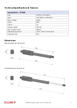
Page 6: ...ns Retracted Gate Arm Dimensions Extended Gate Arm Dimensions Specifications GTR099 Fuse F5L250V or F5AL250V Input 120V 60Hz or 230V 50Hz Motor voltage 24VDC Power 80W Current 3A Actuator speed 16mm s...

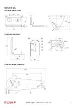
Page 7: ...GTR099 swing gate opener manual Revision 22 7 Dimensions Gate Bracket Dimensions Post Bracket Dimensions Post Pivot Bracket Dimensions...

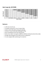
Page 8: ...failure Stop in case of obstruction during gate opening Reverse in case of obstruction during gate closing Built in adjustable auto close 0 100 seconds Built in max Motor running time MRT for additio...

Page 9: ...e Post Brackets are curved When mounting the Post Brackets use bolts long enough to pass through the entire post M10 x 200 bolts are included Concrete anchors are not provided When mounting the Post B...

Page 10: ...gate for a given A and B For example if A is 15cm and B is 20cm the maximum opening angle of the gate is 110 Pull to Open Installation Gate in Closed position Moving Rod is extended Note for best perf...

Page 11: ...sert the M10 x 30 bolt through the centre hole of the post bracket and post pivot bracket as shown Place a 10 washer 10 lock washer and M10 nut on the bottom of the bolt and hand tighten 2 Attach the...

Page 12: ...osition the Post Bracket Assembly and Gate Bracket so that the gate opener is level While holding the gate opener in the level position temporarily secure it with two C clamps 5 Make sure that there i...

Page 13: ...cket assemblies and the gate bracket It allows slight adjustments to the post bracket Then remove the post bracket and gate bracket by taking off the C clamps Please Note Each swing arm contains an in...

Page 14: ...holes in the gates 10 Cut off any part of the bolts that extend beyond the tightened nuts 11 With the gate opener fully retracted and with the gate in the fully open position for Pull to Open install...

Page 15: ...from the hinge point will make the gate stop at a later point when closing To adjust the limit switch use a screwdriver to loosen the screw of Limit Switch A slide to the correct position and then tig...

Page 16: ...e note the wire connection of them is very important Incorrect wire connection may damage the control board The battery used should be waterproof or you should place them in a waterproof case Please e...

Page 17: ...charge controller refer to website for solar panel and battery connections You can plug the transformer into the electrical outlet after all the wire connections are completed Use a surge protector wi...

Page 18: ...GTR099 swing gate opener manual Revision 22 18 Connection of the Control Board...

Page 19: ...o MOTOR terminal 18 the blue wire into DLMT terminal 19 the green wire into COM terminal 20 and the yellow wire into ULMT terminal 21 2 Battery optional The 24V of the battery should be wired to the B...

Page 20: ...use an optional external receiver How to use the Remote to Operate your Gate Opener Each remote has four buttons from top to bottom are separately A B C and D You may use this remote to operate as ma...

Page 21: ...lose function enable disable photobeam function DIP Switch 1 Select push pull to open If the gate opens INTO the property pull to open the DIP Switch is set to OFF factory default setting If your gate...

Page 22: ...o decrease the stall force Potentiometer B Used to adjust the auto close time of the gate opener Turn the potentiometer clockwise to increase the auto close time and turn it counter clockwise to decre...

Page 23: ...the force 2 Disconnect the gate from the gate operator and check that the gate slides freely without any binding Gate opener does not run when you press the remote control 1 Make sure the connection...

Page 24: ...12v charger to recharge your battery When recharging your battery always remember to connect the positive charger red output to the positive battery terminal The negative charger output black connects...

Reviews: