GTR211 Installation Manual:
Rev 1
24
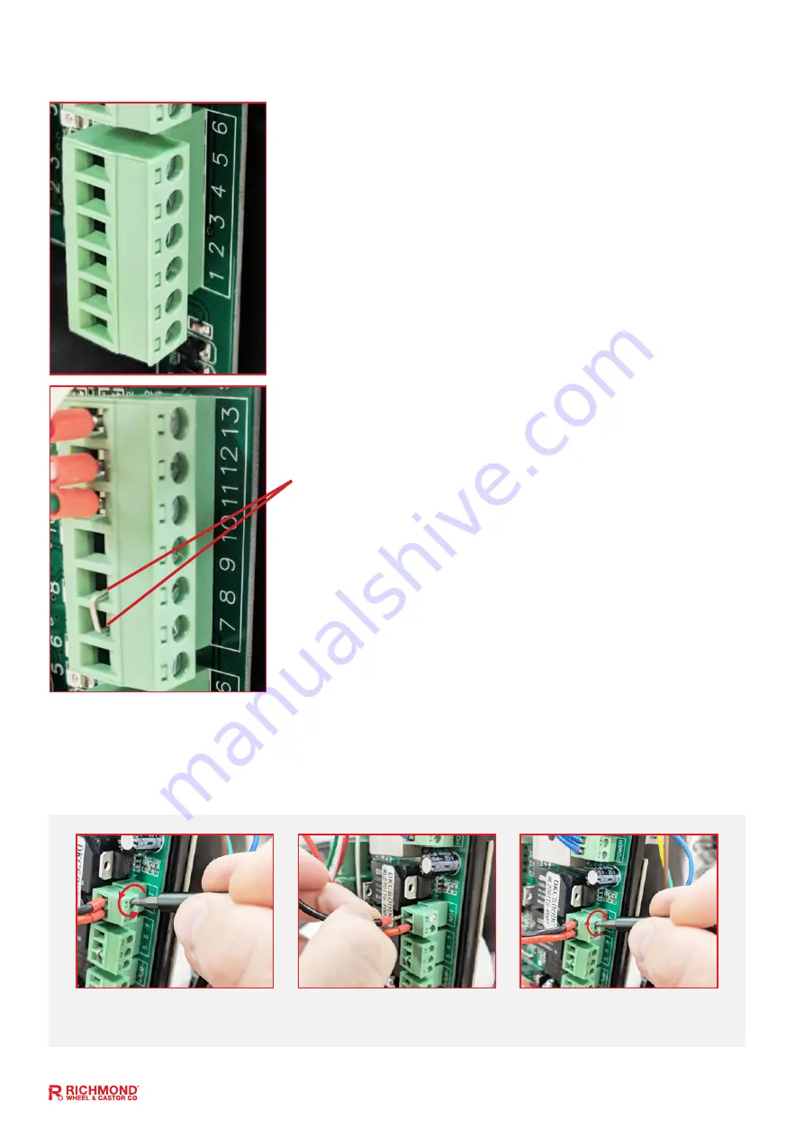
J2 Terminal:
Terminal 1:
Optional External Close Push Button Switch.
Terminal 2:
Optional External Open Push Button Switch.
Terminal 3:
Optional External Stop Push Button Switch.
Terminal 4:
Common Terminal for All Optional Push Buttons.
(Hard-Wired keypad connection between terminals 4 & 5)
Terminal 5:
Optional External Open/Stop/Close Single Push Button
(does the 3 open/stop/close functions)
Terminal 6:
Optional External Push Button Pedestrian Switch
Using a screwdriver, loosen the
screw on the side of the terminal.
Insert the wire into the terminal.
Refer to pages 20 & 21
Tighten with a screwdriver to
secure the wire in place.
How to secure a wire to the circuit board terminals
Ensure that power is off before completing any wiring
All changes to these settings must be completed by a licensed electrician
Please Note: If changing gate direction terminals 11 & 13 on Terminal J5 will need to be swapped.
J5 Terminal: Limit Switch and Accessories
Terminal 7:
Power supply for accessories of J5 (+15V)
Terminal 8:
Photocell input (Normally Closed). If no photocell
is fitted use jumper between terminals 8 & 9.
Terminal 9:
Ground/Earth (GND)
Terminal 10:
Exit wand connection between terminals 9 & 10
Terminals 11, 12, and 13 are factory fitted (pre-wired)
Terminal 11:
Close spring limit switch
Terminal 12:
Spring limit switch common terminal
Terminal 13:
Open spring limit switch


