background image


23 


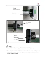
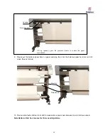
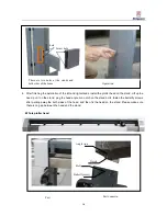
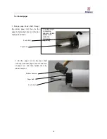
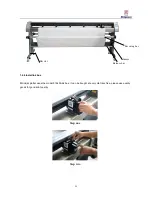
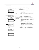
6.  After  pulling  out  the  paper,  please  make  the  paper  roll  stillness,  pull  the  paper  evenly,  make  sure  the 

pulling strength is the same on the both sides of paper and then stick the paper on the receive shaft from 

middle to both sides. We can stick the paper by 3-5 times, but the sticking times are different by different 

paper. (Please follow the picture as follows) 

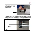
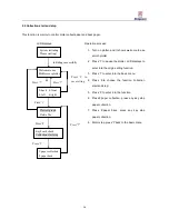
7. Rotate roll shaft manually for 5-8 circles. 


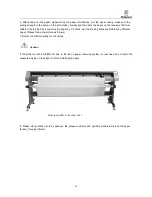
Caution: 


If  the  plotter  model  is  RP-

MJ135, due to there‟s no  paper receiving system, so just need us  put  down the 

pressure wheels on the paper to finish installing the paper. 


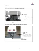
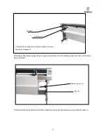
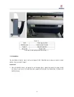
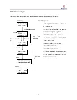
8.  Please  lift  up  rotation  pole  by  spanner,  the  pressure  wheels  and  grinding  wheels  will  press  the  paper 

tensely. (See as follows). 

From the middle to the other sides 


Summary of Contents for RF-MJ135

Page 1: ...Plotter User s Manual Richpeace Group Co Limited Tianjin Richpeace Computer Machinery Co LTD 6 301800 Factory Address No 6 Baozhong Road Baodi Economic Development Zone Tianjin City China Website www...

Page 2: ...d installation of MJ135 plotter 26 1 5 1 Structure and parts functions 26 1 5 2 Installation 27 1 6 Connect to computer 28 Chapter2 Basic setting and operation 30 2 1 Origin setting 31 2 2 Plot test g...

Page 3: ...otice proceedings please understand the difference DANGER The notice means DANGER if ignored it maybe cause deadliness or serious damage to operator WARNING The notice means WARNING if ignored it mayb...

Page 4: ...ain by unfamiliar person It is forbidden to disassemble maintain or refit the plotter These actions might cause electrical attack or fire by creepage Touch the high voltage accessory of the plotter mi...

Page 5: ...ause electrical attack or fire by creepage Please don t touch the print head and the moving parts when plotting These actions might cause body injured When the plotter stops working please keep your h...

Page 6: ...t weaken the capability of the machine Don t use the plotter at the places that have mechanical shake or electrical noise Using the plotter in these places might weaken the capability of the plotter D...

Page 7: ...These actions might weaken the capability of the plotter Make sure there is enough space for working or else it might cause plotting error If touch the machine it might cause plotting error Use indoor...

Page 8: ...all Plotter 1 1 Check the accessory 1 2 Technical parameter 1 3 Structure and installation of new model plotter 1 4 Structure and installation 1 5 Structure and installation of MJ 135 plotter 1 6 Conn...

Page 9: ...missing If there has missing accessory please contact the salesman or Richforever authorized local agent Power cable one piece USB data cable one piece Bolt M6 40 flat spring washer 4 sets Allen key...

Page 10: ...h one set Beam one set Roll shaft and feed shaft each one set Paper hold one set two pieces Balance paper bar two pieces MJ135 with one piece Bolt M6 20 4 pieces bar 2 pieces new model plotter Square...

Page 11: ...edium type 30 60g paper Communication USB port LAN port Motor type Servo motor Data format HPGL Environmental conditions demand Power AC220V 110V 50Hz 10 Storage temperature 20 50 Working temperature...

Page 12: ...receiving system are on same side save space low the roll motor near ground it is more convenient to install paper Add two pieces of bar back of plotter Stand foot Pressure wheel devic Print head Lef...

Page 13: ...her into the six angle bolt See as follows 2 Lay down the four stand feet of the left and right stands to make it balanced 3 Plug the bolts into the hole at right stand fix the right stand with the be...

Page 14: ...on notch on the stand bolts fasten the butterfly screws after putting away the both sides of the head and then fix the head on the stand Please make sure there is no gap between the head and the stand...

Page 15: ...into the aviation socket of the plotter Fig2 Aviation socket Motor Plug the motor cables at the left stand into the aviation sockets on the left side of the plotter head Figure 1 Figure 2 Plug the se...

Page 16: ...Rubber hammer Paper hub Feed shaft 2 Put the paper roll on the feed shaft correctly push fast paper hub into the core of paper roll and then fasten them by rubber hammer 3 Fasten screws with Allen key...

Page 17: ...pressure wheels and put the paper through the plotter head after paper roll is installed on plotter correctly please note to lift up the pressure wheels then pull paper to the front of the plotter Ple...

Page 18: ...o both sides We can stick the paper by 3 5 times but the sticking times are different by different paper Please follow the picture as follows 7 Rotate roll shaft manually for 5 8 circles 8 Please lift...

Page 19: ...both sides See as follows 10 Please rotate feed shaft and roll shaft to make balance paper bars between top and bottom sensors Installation of ink box is same for three model plotters Lift up spanner...

Page 20: ...best printing paper height 1 4 Structure and installation At present our company produces three kinds of plotters with different structure common model roll shaft and feed shaft are on different sides...

Page 21: ...he pressure wheels are not on grinding wheels plotter paper will not move At the time please check whether the pressure wheels are under the green labels Please make sure balance paper bars are betwee...

Page 22: ...regularly by toothbrush never use the steel brush Table 1 1 Motor Control receiving and feeding paper Pressure wheel Control paper moving when plotting Print head Drive ink boxes left right when plott...

Page 23: ...Function confirm the modifications that had been modified Function It is used to set number likes other number key Function used to enter into basic menu Power outlet Com switch PPPower outlet Connect...

Page 24: ...her into the six angle bolt See as follows 2 Lay down the four stand feet of the left and right stands to make it balanced 3 Plug the bolts into the hole at right stand fix the right stand with the be...

Page 25: ...on notch on the stand bolts fasten the butterfly screws after putting away the both sides of the head and then fix the head on the stand Please make sure there is no gap between the head and the stand...

Page 26: ...e into the aviation socket of the plotter Fig2 Plug the sensor cable at the left stand into the aviation socket on the left side of the plotter head LAN port cable USB port Sensor aviation cable Aviat...

Page 27: ...t paper hub into the core of paper roll and then fasten them by rubber hammer Feed shaft Paper hub 1 Plunge paper feed shaft through the plotter paper roll then fix the paper by fastening hubs on both...

Page 28: ...ig1 then put the right side of paper feed shaft into the feed shaft seat please let the motor driver completely plunge into the right side of the Feed Shaft Please following fig2 3 Fasten screws with...

Page 29: ...s and put the paper through the plotter head after paper roll is installed on plotter correctly please note to lift up the pressure wheels then pull paper to the front of the plotter Please follow the...

Page 30: ...but the sticking times are different by different paper Please follow the picture as follows 7 Rotate roll shaft manually for 5 8 circles Caution If the plotter model is RP MJ135 due to there s no pap...

Page 31: ...alance paper bar slots on both sides See as follows 10 Please rotate feed shaft and roll shaft to make balance paper bars between top and bottom sensors Running pole Spanner Lift up spanner press the...

Page 32: ...Install ink box MJ inkjet plotter uses the model 51645Aink box it can be bought at every Hp franchise please use quality goods for good print quality Step one Step two Receiving bar Sensor Balance bar...

Page 33: ...ack that means no ink you should change the ink box immediately if there shows green that means the ink is full 1 5 Structure and installation of MJ135 plotter 1 5 1 Structure and parts functions As f...

Page 34: ...2 Installation The installations of stand head ink box and paper for MJ 135plotter are as same as common model plotters here we wouldn t repeat Install cloth 1 Take off butterfly screws put support o...

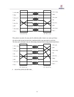
Page 35: ...otter is using the LAN cable port and USB port you can connect the LAN cable to the computer or to the router the LAN cable must be twist pair If the plotter connects to the router the cable should be...

Page 36: ...hite blue orange white brown brown RJ45 Modular Plugs RJ45 Modular Plugs 2 connect the plotter with USB cable 1 white orange 2 orange 3 white green 4 blue 5 white blue 6 green 7 white brown 8 brown 3...

Page 37: ...Chapter2 Basic setting and operation 2 1 Origin setting 2 2 Plot test graph 2 3 Delete file 2 4 Sensor check 2 5 Keyboard check 2 6 Collection start and stop 2 7Print head cleaning times 2 8Version in...

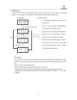
Page 38: ...g and return to main screen Press 1 to enter into the basic operation menu Caution If the origin is not set correctly it may cause the marker is not totally plot on the paper if the origin position is...

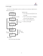
Page 39: ...plotter LCD displays to enter into the origin setting function 3 Press 1 to enter into the basic menu 4 Press 5 to plot test graph Caution Don t plot test graph when plotting Press 5 Return automatica...

Page 40: ...to enter into the function delete file 5 Press 7 to exit press 5 to delete the current file and return to the basic menu Caution The deleted file will be deleted from the plotcenter and the next file...

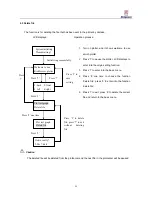
Page 41: ...Press 8 twice to choose the function Sensor check press 5 to enter into the function 4 Blocking the top sensor of the roll shaft side screen shows roll paper over the bottom sensor of the roll shaft...

Page 42: ...o choose the function keyboard check press 5 to enter into the function 5 Press the key that the screen show screen will show the wrong key If it shows press 2 but you press 4 it will show warning the...

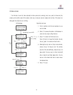
Page 43: ...oose the function collection start and stop 5 Press 5 to enter into the function 6 Press 2 paper collection press any key stop paper collection 7 Press 8 paper back press any key stop paper collection...

Page 44: ...ose the function Print head cleaning times 5 Press 5 to enter into the function 6 Press 2 the number add 1 7 Press 8 the number decrease 1 8 Press 5 keep the revised number and exit 9 Press 7 back to...

Page 45: ...nto the origin setting function 3 Press 1 to enter into the basic menu 4 Press 8 four times to choose the function version info 5 Press 5 to enter into the function 6 Press 7 to exit Press 7 2 back 8...

Page 46: ...39 Chapter3 Plot 3 1 Plotcenter 3 2 File 3 3 Tools 3 4 Language 3 5 Setup 3 6 Calibration 3 7 Plot sequence 3 8 Print preview 3 9Operations after plotting...

Page 47: ...er to modify the calibration of the HPGL file please refer to 3 6 Calibration 3 2 File 1 Link If the plotcenter can connect to the plotter it will show connect successfully If the IP is not set correc...

Page 48: ...41 3 Open Open the HPGL file you want to plot Operation process as follows 1 Click the open menu in the plot menu 2 Popup open dialogue choose the needed files...

Page 49: ...Plot click plot to start plotting For example the plotting is suddenly stopped because of the plotter power is off then we don t need to plot the total marker again only need to click exit and save t...

Page 50: ...Test It can plot out a test graph 5 Pause It can stop sending data which is in the plotting sequence Choose the file which needs pause then click pause After pause the file will change from wait to p...

Page 51: ...he plotter will turn to the main screen Operation process as follows 1 Choose delete menu in the plot menu delete the file 2 Click Delete the following dialogue will appear 3 Press Yes to delete the f...

Page 52: ...it will indicate as follows 3 3 Tools 1 Input parameter Input the mainboard parameter from the file PlotPara ini in the plotcenter folder 2 Output parameter Output the mainboard parameter to the file...

Page 53: ...the plotting files to the plotcenter to achieve the network plotting 4 History The plotting history of the plotter Click History to get the following dialog it will show you all the information that y...

Page 54: ...47 3 4 Language We have two Languages for you to choose English and Simplified Chinese...

Page 55: ...nd LAN will change to gray color that means connection is normal and it can start to plot USB communication if the plotter is using the USB cable communication we need to change the options in the fol...

Page 56: ...168 1 A 255 255 255 0 192 168 1 1 the plotter plotcenter IP should be 192 168 1 B 255 255 255 0 192 168 1 1 A and B must be different If all IP set up correct open plotcenter again the number of set u...

Page 57: ...the cursor press 2 or 8 to add reduce the values 6 Press 5 to save the modified values press 7 to return back to the previous menu without saving modified values 7 Press 5 to save the modified values...

Page 58: ...it can t connect to each other Operation process as follows 1 Open the Setup menu in the plotcenter 2 Choose Network in the communications setting menu interface shows as follows 3 Modify the paramet...

Page 59: ...idth set the plotting line width Paper width set the maximum plotting width if the marker width is wider than the paper width the marker will be split to several parts and plot out Border and Space Ri...

Page 60: ...ey must be together when using two ink boxes If you use only one ink box just choose no 1 If we use four ink boxes we can choose 1 2 3 4 together Bidirectional printing error setup set the shift betwe...

Page 61: ...meter rectangle and measure the length and width 2 Choose the plotter setup under the setup menu and popup the plotter setup window 3 Input the actual length and width that you have measured to plotte...

Page 62: ...that is not sending the function of the file will be shown in the under four functions forward backward head and tail is used to change the sequence of the files when the data is not sending Caution f...

Page 63: ...file when one marker is finished you can also send the other file without close the plotcenter If you want to finish plotting you can take out the balance bar and cut off the paper the cutting positio...

Page 64: ...57 Chapter4 trouble shooting 4 1 Error indication 4 2 Note...

Page 65: ...eans the sensor is damaged Solution Check the origin sensor whether it is damaged check the print head whether it works fine Note if the problem is still there when restarting the machine several time...

Reviews: