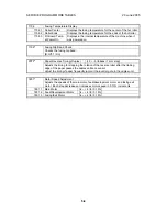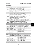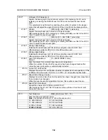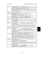
SERVICE PROGRAM MODE TABLES
20 June 2005
5-12
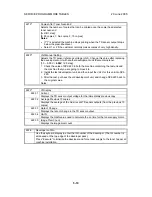
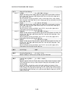
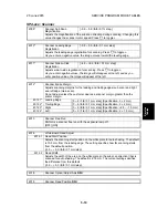
2309*
Transfer Current Correction
Paper Lower Width (a)
[0 ~ 297 /
150
/ 1 mm step]
2309 1
Adjusts the lower paper width threshold for the transfer current, charge voltage,
and development bias corrections.
Use this SP when an image problem (e.g., insufficient toner transfer) occurs with a
small width paper. If the paper width is smaller than this value, the transfer current
will be multiplied by the factor in SP2-309-3 (paper tray) or SP2-309-5 (by-pass).
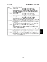
Paper Upper Width (b)
[0 ~ 297 /
216
/ 1 mm step]
2309 2
Adjusts the upper paper width threshold for the transfer current, charge voltage,
and development bias corrections.
As for SP2-309-1, but the factors are in SP2-309-4 (paper tray) and SP2-309-6
(by-pass).
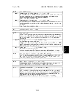
Paper Tray (alpha)
[1.0 ~ 3 /
1.2
/ 0.1 mm step]
2309 3
Adjusts the transfer current correction coefficient used if the paper width is less
than the setting of SP2-309-1.
Paper Tray (beta)
[1.0 ~ 3 /
1.2
/ 0.1 mm step]
2309 4
Adjusts the transfer current correction coefficient used if the paper width is less
than the setting of SP2-309-2.
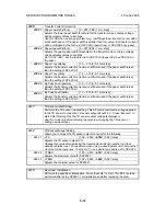
By-Pass Feed (gamma)
[1.0 ~ 3 /
1.5
/ 0.1 mm step]
2309 5
Adjusts the transfer current correction coefficient used if the paper width is less
than the setting of SP2-309-1.
By-Pass Feed (delta)
[1.0 ~ 3 /
1.5
/ 0.1 mm step]
2309
6
Adjusts the transfer current correction coefficient used if the paper width is less
than the setting of SP2-309-2.
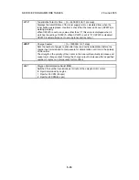
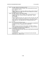
TD Sensor Initial Setting
2801
*
Performs the TD sensor initial setting. This SP mode controls the voltage applied
to the TD sensor to make the TD sensor output about 4.0 V. Press “Execute” to
start. After finishing this, the TD sensor output voltage is displayed.
Use this mode only after installing the machine, changing the TD sensor, or
adding new developer.
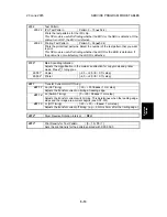
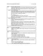
TD Sensor Manual Setting
2802
*
Allows you to adjust the TD sensor output manually for the following.
VTS
[1.00 ~ 5.00V /
4.78V
/ 0.02V step]
2802 1
Adjusts the TD sensor output (VT).
Change this value after replacing the development unit with another one that
already contains toner. For example, when using a development unit from another
machine for test purposes. To adjust VT, use a similar procedure as for SP2-220.
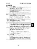
VTMAX
[1.00 ~ 5.00V /
4.78
V / 0.02V step]
2802 2
Adjusts the maximum value for SP2802 1.
VTMIN
[1.00 ~ 5.00V /
1.00V
/ 0.02V step]
2802 3
Adjusts the minimum value for SP2802 1.
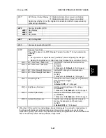
Developer Initialization
2805
*
Performs the developer initialization. Press “Execute” to start. This SP should be
performed after doing SP2801-1 at installation and after replacing the drum.


