


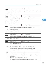


2101 4
Right side
[0.0 to 9.0 / 2.0 / 0.1 mm/step] ( Copy Adjustments
Printing/Scanning)
Specification: 2 +2.5/–1.5 mm
Adjusts the right edge erase margin. The rear right edge is this value plus 0.3 mm.
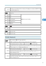
2201*
Development Bias Adjustment
2201 1
Printing
[–1500 to –200 / –650 / 1 V/step]
Adjusts the voltage applied to the development roller when printing. This can be adjusted
as a temporary measure if faint copies are being produced due to an aging drum.
2201 2
ID sensor pattern
[–2 = LL (220 V) / -1 = L (260 V) / 0 = N (300 V) / 1
= H (340 V) / 2 = HH (380 V)]
Adjusts the voltage applied to the development roller when generating the ID sensor
pattern. The actual voltage applied is this setting plus the value of SP 2201 1. The setting
affects ID sensor pattern density, which in turn affects the toner supply.
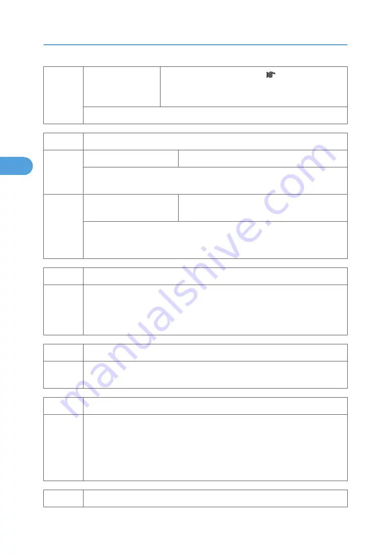
2213*
Outputs after Near End
2213 1
[0 = 50 pages / 1 = 20 pages]
Sets the number of copy/print pages that can be made after toner near-end has been
detected. Reduce the number of pages if the user normally makes copies with a high image
ratio.
2214
Developer Initialization
2214 1
Initializes both the TD sensor toner supply target voltage and the TD sensor gain value.
Carry this out after replacing the developer or the TD sensor.
2220
TD Sensor Output Value Display
2220 1
Displays:
Vt: the current TD sensor output value and
Vref: the target TD output value Vts (SP 2926) + correction for ID sensor output.
The TD sensor output value changes every copy. If 1 > 2, toner is supplied to the
development unit.
2221
ID Sensor Error Analysis
3. Appendix: SP Mode Tables
26
3
Summary of Contents for Aficio MP 1600L2
Page 1: ...Model K C3 5L Machine Code B244 B276 B277 B268 B269 Field Service Manual 3 December 2010 ...
Page 2: ......
Page 12: ...10 ...
Page 14: ...Machine Configuration 1 Product Information 12 1 ...
Page 20: ...1 Product Information 18 1 ...
Page 70: ...2 Installation 68 2 ...
Page 71: ...3 Preventive Maintenance PM Tables See Appendices for the PM Tables 69 3 ...
Page 74: ...7 Wait until the message Completed shows 8 Quit the SP mode 3 Preventive Maintenance 72 3 ...
Page 139: ...PSU Power Supply Unit 1 Left cover p 79 2 PSU A All connectors x 6 Other Replacements 137 4 ...
Page 151: ...SP Mode Tables See Appendices for the SP Mode Tables SP Mode Tables 149 5 ...
Page 171: ...1 1 0 0 A5 SEF 1 1 1 0 B5 SEF 1 Detected Using SP Modes 169 5 ...
Page 207: ...Model K C3 5L Machine Code B244 B276 B277 B268 B269 Appendices 3 December 2010 ...
Page 208: ......
Page 210: ...2 ...
Page 228: ...2 Appendix Preventive Maintenance 20 2 ...
Page 262: ...MEMO 54 ...
Page 263: ...MEMO 55 ...
Page 264: ...MEMO 56 EN ...


