background image

Main Motor

1. Rear cover ( p.76)
2. Main motor [A] (  x 4, 

 x 1)

Rear Exhaust Fan (B244/B269/B277 Only)

1. Rear cover ( p.76)
2. Rear exhaust fan [A] (  x 2, 

 x 1)

• Reassembling -

Other Replacements

135

4

Summary of Contents for Aficio MP 1600L2

Page 1: ...Model K C3 5L Machine Code B244 B276 B277 B268 B269 Field Service Manual 3 December 2010 ...

Page 2: ......

Page 3: ... while the copier is operating Be careful to avoid touching those components with your bare hands Health Safety Conditions Toner and developer are non toxic but if you get either of them in your eyes by accident it may cause temporary eye discomfort Try to remove with eye drops or flush with water as first aid If unsuccessful get medical attention Observance of Electrical Safety Standards The copi...

Page 4: ...is is not repairable in the field Customer engineers are therefore directed to return all chassis and laser subsystems to the factory or service depot when replacement of the optical subsystem is required Use of controls or adjustment or performance of procedures other than those specified in this manual may result in hazardous radiation exposure WARNING FOR LASER UNIT WARNING Turn off the main sw...

Page 5: ...d Abbreviations This manual uses several symbols and abbreviations The meaning of those symbols and abbreviations are as follows See or Refer to Clip ring Screw Connector SEF Short Edge Feed LEF Long Edge Feed 3 ...

Page 6: ...Environment 19 Machine Level 20 Minimum Space Requirements 20 Power Requirements 21 Copier Installation 22 Power Sockets for Peripherals 22 Accessory Check 22 Installation Procedure 23 Platen Cover Installation 28 Accessory Check 28 Installation Procedure 28 ARDF Installation 29 Accessory Check 29 Installation Procedure 30 ADF Installation 33 Accessory Check 33 Installation Procedure 34 Two tray P...

Page 7: ...ey Counter Installation 57 Optional Counter Interface Unit Type A B870 11 60 Accessory Check 60 Installation Procedure 60 DDST Unit Type F B865 62 Accessory Check 62 Installing Expansion Component 62 Network Interface Board D564 64 Component Check 64 Installing Expansion Component 64 3 Preventive Maintenance PM Tables 69 How to Reset the PM Counter 70 4 Replacement and Adjustment General Cautions ...

Page 8: ...nly 83 Right Lower Cover Two tray Models Only 83 Platen Cover Sensor 84 Scanner Unit 85 Exposure Glass DF Exposure Glass 85 Lens Block 86 Lamp Stabilizer Board And Exposure Lamp 87 Original Width Length Sensor 87 Scanner Motor 89 Scanner Home Position Sensor 90 Adjusting Scanner Positions 90 Laser Unit 95 Location of Caution Decal 95 Toner Shield Glass 96 Laser Unit 96 LD Unit 97 Polygonal Mirror ...

Page 9: ... By Pass Paper Size Switch 114 Registration Clutch 115 Registration Sensor 115 Upper Paper Feed Clutch and By Pass Feed Clutch 116 Relay Clutch 117 Relay Sensor 117 Lower Paper Feed Clutch Two tray Models Only 118 Vertical Transport Sensor Two tray Models Only 118 Paper Size Switch 119 Image Transfer 120 Image Transfer Roller 120 Image Density Sensor 121 Fusing 122 Fusing Unit 122 Thermistor 122 F...

Page 10: ...CU Base Engine Image Control Unit 134 Main Motor 135 Rear Exhaust Fan B244 B269 B277 Only 135 Left Exhaust Fan 136 PSU Power Supply Unit 137 Gearbox 138 Copy Adjustments Printing Scanning 141 Printing 141 Scanning 143 ADF Image Adjustment 145 5 System Maintenance Service Program Mode 147 How to Enter the SP Mode 147 SP Mode Tables 149 Using SP Modes 150 Adjusting Registration and Magnification 150...

Page 11: ... SP 6901 168 Firmware Update Procedure 170 Engine BICU Firmware Update Procedure 170 GDI Printer Scanner Update Procedure 171 6 Troubleshooting Service Call Conditions 177 Summary 177 SC Code Descriptions 178 Electrical Component Defects 193 Sensors 193 Switches 195 Blown Fuse Conditions 197 LED Display 198 BICU 198 7 Energy Saving Energy Save 199 Energy Saver Modes 199 Paper Save 203 Effectivenes...

Page 12: ...10 ...

Page 13: ...1 Product Information Specifications See Appendices for the following information General Specifications Supported Paper Sizes Option Equipment 11 1 ...

Page 14: ...Machine Configuration 1 Product Information 12 1 ...

Page 15: ...l B406 B ADF optional B813 A ARDF optional B814 A Paper tray unit 1 tray optional B385 F Paper tray unit 2 trays optional B384 E 1 bin tray optional B621 H GDI GDI controller standard for B244 or optional for B268 B269B276 B277 B865 I The optional GDI controller comes with a dedicated controller box and printer scanner panel Machine Configuration 13 1 ...

Page 16: ...Overview Component Layout The above illustration is the B244 B269 B277 model B268 B276 No duplex unit one paper tray 1 Product Information 14 1 ...

Page 17: ...er 17 OPC Drum 18 Middle Transport Roller 19 Duplex Exit Sensor 20 Image Density Sensor 21 Registration Roller 22 Registration Sensor 23 By pass Tray 24 Lower Transport Roller 25 Upper Relay Roller 26 Relay Sensor 27 Lower Relay Roller 28 Vertical Transport Sensor 29 Paper Feed Roller 30 Paper End Sensor 31 Bottom Plate 32 PCU 33 Development Roller 34 WTL 35 Polygon Mirror Motor 36 Laser Unit 37 T...

Page 18: ...Paper Path The B244 B269 B277 model has a duplex unit mounted on the right side of the machine All models have a by pass tray 1 Product Information 16 1 ...

Page 19: ... Layout 1 Scanner Motor 2 Main Motor 3 Hot Roller 4 OPC Drum 5 Development Roller 6 Relay Clutch 7 Lower Paper Feed Clutch 8 By pass Feed Clutch 9 Upper Paper Feed Clutch 10 Registration Clutch Overview 17 1 ...

Page 20: ...1 Product Information 18 1 ...

Page 21: ...rn off the main switch and disconnect the power cord the telephone line and the network cable Environment Temperature and Humidity Chart Temperature Range 10 C to 32 C 50 F to 89 6 F Humidity Range 15 to 80 RH Ambient Illumination Less than 1 500 lux do not expose to direct sunlight Ventilation 3 times hr person or more Ambient Dust Less than 0 075 mg m3 2 0 x 10 6 oz yd3 19 2 ...

Page 22: ...on over 2 000 m 6 560 ft above sea level Place the machine on a strong and level base Inclination on any side should be no more than 5 mm Do not place the machine where it is subjected to strong vibrations Machine Level Front to back Within 5 mm 0 2 of level Right to left Within 5 mm 0 2 of level Minimum Space Requirements Place the copier near the power source providing clearance as shown A front...

Page 23: ... the front of the machine Power Requirements Make sure that the wall outlet is near the machine and easily accessible After completing installation make sure the plug fits firmly into the outlet Avoid multi wiring Be sure to ground the machine Input voltage Taiwan 110 120 V 60 Hz 12 A Europe Asia China 220 240 V 50 60 Hz 7 A Installation Requirements 21 2 ...

Page 24: ...s A Socket for ADF ARDF Rated voltage output max DC24 V B Socket for paper tray unit Rated voltage output max DC24 V Accessory Check Check that you have the accessories in this list Basic Machines No Description Q ty 1 NECR English Multi language 1 2 EU Safety Sheet 1 3 Laser Decal 1 2 Installation 22 2 ...

Page 25: ...g Instructions 1 5 General Setting Guide 1 6 Copy Reference 1 7 Printer Scanner Reference 1 8 Network Reference 1 9 Quick Guide Copy Edition 1 10 Quick Guide Printer Scanner Edition 1 11 Manual for this machine 1 12 Safety Information 1 Installation Procedure Unplug the machine power cord before starting the following procedure Copier Installation 23 2 ...

Page 26: ...1 Remove filament tape and other padding 2 Open the front door and remove the toner bottle holder A 2 Installation 24 2 ...

Page 27: ...oto conductor unit C 4 Separate the PCU into the upper part and the lower part x 5 5 Put a sheet of paper on a level surface and place the upper part on it This prevents foreign material from getting on the sleeve rollers Copier Installation 25 2 ...

Page 28: ...ed screwdriver Do not turn the gear E too much The developer may spill 7 Reassemble the PCU and reinstall it 8 Shake the toner bottle F several times Do not remove the bottle cap G before you shake the bottle 9 Remove the bottle cap G and install the bottle on the holder Do not touch the inner cap H 10 Set the holder with the toner bottle in the machine 2 Installation 26 2 ...

Page 29: ...in the main power cord and turn on the main switch 14 Activate the SP mode and execute Devlpr Initialize SP 2214 1 15 Wait until the message Completed shows about 45 seconds 16 Activate the User Tools and select the menu Language 17 Specify a language This language is used for the operation panel 18 Load the paper in the paper tray and make a full size copy and make sure the side to side and leadi...

Page 30: ...Check Check that you have the accessories indicated below No Description Q ty 1 Stepped Screw 2 Installation Procedure Unplug the machine power cord before starting the following procedure Install the platen cover x 2 2 Installation 28 2 ...

Page 31: ...e accessories against the following list No Description Q ty 1 Scale Guide 1 2 DF Exposure Glass 1 3 Stud Screw 2 4 Knob Screw 2 5 Original Size Decal 2 6 Screwdriver Tool 1 7 Attention Decal Top Cover 1 8 Stamp Cartridge 1 9 Installation Procedure 1 ARDF Installation 29 2 ...

Page 32: ...left scale A x 2 3 Place the DF exposure glass B on the glass holder Make sure that the white mark C is on the bottom at the front end 4 Peel off the backing D of the double sided tape attached to the rear side of the scale guide E then install the scale guide x 2 removed in step 2 5 Install the two stud screws F 2 Installation 30 2 ...

Page 33: ...e the ARDF unit with the knob screws G 8 Connect the cable H to the copier 9 Attach the appropriate original size decal I as shown 10 Attach an attention decal to the top cover The attention decals in the package are written in different languages ARDF Installation 31 2 ...

Page 34: ...cartridge K to the ARDF 3 Make a full size copy and check that the side to side and leading edge registrations are correct If they are not adjust the side to side and leading edge registrations p 145 ADF Image Adjustment 2 Installation 32 2 ...

Page 35: ... accessories against the following list No Description Q ty 1 Scale Guide 1 2 DF Exposure Glass 1 3 Stud Screw 2 4 Fixing Screw 2 5 Original Size Decal 2 6 Screwdriver Tool 1 7 Attention Decal Top Cover 1 8 Stamp Cartridge 1 9 Installation Procedure 1 ADF Installation 33 2 ...

Page 36: ...F exposure glass B on the glass holder Make sure that the white mark C is on the bottom at the front end 4 Peel off the backing D of the double sided tape attached to the rear side of the scale guide E then install the scale guide x 2 removed in step 2 5 Install the two stud screws F 6 Mount the ADF on the copier and then slide it to the front 2 Installation 34 2 ...

Page 37: ...ing screws G 8 Connect the cable H to the copier 9 Attach the appropriate scale decal I as shown 10 Attach an attention decal to the top cover The attention decals in the package are written in different languages ADF Installation 35 2 ...

Page 38: ...ower switch on Then check if the document feeder works properly 14 Make a full size copy and check that the side to side and leading edge registrations are correct If they are not adjust the side to side and leading edge registrations p 145 ADF Image Adjustment 2 Installation 36 2 ...

Page 39: ...Description Q ty 1 Screw M4x10 10 2 Unit Holder 2 x 2 pieces 3 Adjuster 1 4 Unit Holder 2 Installation Procedure If the optional printer unit is installed Print out all data in the printer buffer Disconnect the network cable Unplug the machine power cord before starting the following procedure Two tray Paper Tray Unit Installation 37 2 ...

Page 40: ...of cardboard After removing the tape that secures the peripheral components and cardboard to the paper tray make sure that there is no tape and or tape reside remaining on the tray 2 Attach the adjuster A to the base plate as shown This step is not necessary if a cabinet is installed 2 Installation 38 2 ...

Page 41: ... the copier on the paper tray unit Before placing the copier on the paper tray unit make sure that the harness C is safe The paper tray unit does not function properly if the harness is damaged Two tray Paper Tray Unit Installation 39 2 ...

Page 42: ...277 Remove the 2nd tray cassette D 6 Install the two screws E 7 Reinstall the tray cassette 8 Install the two brackets F x 1 each 9 Connect the connecting harness G to the copier There are cutouts for the plugs on both sides The left side has one cutout and the right side has two 2 Installation 40 2 ...

Page 43: ...tate the adjuster installed at step 2 to fix the machine in place If a cabinet is installed this step is unnecessary 13 Load the paper in the paper trays and make full size copies from each tray Check if the side to side and leading edge registrations are correct If they are not adjust the registrations p 141 Copy Adjustments Printing Scanning Two tray Paper Tray Unit Installation 41 2 ...

Page 44: ...following list No Description Q ty 1 Screw M4 x 10 2 2 Stepped Screw M4 x 10 2 3 Unit Holder 2 Installation Procedure If the optional printer unit is installed Print out all data in the printer buffer Disconnect the network cable Unplug the machine power cord before starting the following procedure 2 Installation 42 2 ...

Page 45: ...he pieces of cardboard 2 Remove the cover A 1 rivet Before placing the copier on the paper tray unit make sure that the harness B is safe The paper tray unit does not function properly if the harness is damaged 3 Set the copier on the paper tray unit One tray Paper Tray Unit Installation 43 2 ...

Page 46: ...e tray copier model B268 B276 Remove the 1st tray cassette C Two tray copier models B244 B269 B277 Remove the 2nd tray cassette C 5 Install the two screws D 6 Reinstall the tray cassette 2 Installation 44 2 ...

Page 47: ...t side has one cutout and the right side has two 9 Reinstall the cover removed in step 2 10 Load the paper in the paper tray and make full size copies from tray Check if the side to side and leading edge registrations are correct If they are not adjust the registrations p 141 Copy Adjustments Printing Scanning One tray Paper Tray Unit Installation 45 2 ...

Page 48: ...ription Q ty 1 Installation procedure 1 2 One bin sorter 1 3 Exit tray 1 4 Tapping screw M3 x 6 1 Installation Procedure Unplug the machine power cord before starting the following procedure 1 Remove the inverter tray A 2 Remove the rail B 2 knob screws 3 Remove the cover C 1 rivet 2 Installation 46 2 ...

Page 49: ...ect the connector F 7 Cut the front cover as shown to make an opening G for the 1 bin tray 8 Install the 1 bin tray H 9 Make sure the connectors I are connected firmly 10 Fasten the screw 11 Connect the connector J that you removed in step 6 One Bin Tray Installation 47 2 ...

Page 50: ...p the front end higher than the rear end Push the left hook into the opening in the copier Push the right hook into the opening in the copier 15 Pull the support N out of the left end of the exit tray 16 Insert the support into the left end of the paper exit tray O of the copier 17 Turn the main switch on 18 Check the operation 2 Installation 48 2 ...

Page 51: ...edure 1 Remove the exposure glass 2 Remove the left cover 3 Pass the connector A through the opening B 4 Install the anti condensation heater C as shown 5 Join the connectors A D 6 Clamp the harness with the clamp E 7 Reinstall the left cover and exposure glass Anti condensation Heater Installation 49 2 ...

Page 52: ...Tray Heaters Unplug the machine power cord before starting the following procedure Upper Tray Heater 1 Remove the 1st tray cassette A 2 Remove the rear cover 2 Installation 50 2 ...

Page 53: ... the connector B through the opening C and install the tray heater D x 1 4 Install the relay harness E 5 Fix the harness with the clamp F 6 Reinstall the 1st tray cassette and the rear cover Tray Heaters 51 2 ...

Page 54: ... 2 Remove the rear lower cover 3 B244 B269 B277 only Remove the DCB B with bracket x 4 x 3 4 Pass the connector C through the opening D and install the tray heater E x 1 5 Join the connectors F 6 Reinstall the 2nd tray cassette DCB and rear lower cover 2 Installation 52 2 ...

Page 55: ...Tray Heaters For The Optional Paper Feed Units 1 Remove the rear cover A for the paper tray unit One tray paper feed unit Tray Heaters 53 2 ...

Page 56: ...Two tray paper feed unit 2 Two tray unit only Remove the cable guide B 3 Install the clamps C One tray paper feed unit 2 Installation 54 2 ...

Page 57: ...Two tray paper feed unit 4 Pass the connector D through the opening E 5 Install the tray heater F x 1 One tray paper feed unit Tray Heaters 55 2 ...

Page 58: ... Reinstall the cable guide 9 One tray copier model B268 B276 Remove the 1st tray cassette Two tray copier models B244 B269 B277 Remove the 2nd tray cassette 10 Remove the two screws I and install the two hexagonal socket screws J 11 Reinstall the 1st tray 2nd tray s and rear cover 2 Installation 56 2 ...

Page 59: ...e the rear cover 3 Cut the cap A with nippers 4 Punch out the small hole B using a screwdriver 5 Hold the key counter plate nuts C on the inside of the key counter bracket D and insert the key counter holder E 6 Secure the key counter holder to the bracket x 2 7 Install the key counter cover F x 2 Key Counter Installation 57 2 ...

Page 60: ... CN126 on the BICU 9 Hold the harness with the clamps H I J The relay harness is not included in the key counter bracket accessories 10 Join the relay harness K with the connector L 11 Reinstall the rear cover 2 Installation 58 2 ...

Page 61: ...nectors through the opening of the key counter holder assembly P and put the connectors inside the assembly 16 Hook the key counter holder assembly onto the stepped screw N Check that the harness is not caught between the left cover and the key counter holder assembly 17 Secure the key counter holder assembly with the screw Q Key Counter Installation 59 2 ...

Page 62: ...nit Type A B870 11 Accessory Check No Description Q ty 1 Screw M3x6 4 2 Bind 80 mm 1 3 Locking Stud 4 4 Saddle Clamp 1 5 EMC Caution Sheet 1 6 Harness 1 7 ROHS Caution Sheet China only 1 Installation Procedure 2 Installation 60 2 ...

Page 63: ... Locking stud x 4 4 Connect the harness B to CN140 C 13 pins on the BICU 5 Clamp the harness in two places D 6 Connect the harness for the external key counter device to CN4 20 pins on the bridge board A 7 Reattach the rear cover x 6 Optional Counter Interface Unit Type A B870 11 61 2 ...

Page 64: ... Cable 1 3 Tapping Screw M3X6 6 4 Sheet EULA 1 5 Seal Caution 1 6 EMC Caution Sheet 1 7 Caution Sheet 1 8 Installation Procedure 1 Installing Expansion Component Unplug the machine power cord before starting the following procedure 1 Remove the rear cover A x 6 2 Installation 62 2 ...

Page 65: ... BICU 3 Connect the controller box D to the BICU Make sure that the BICU E is not damaged and that the three openings F G H hold the controller box 4 Fasten the screws x 7 5 Re attach the rear cover A x 6 DDST Unit Type F B865 63 2 ...

Page 66: ...DDST Unit Type F B865 Component Check No Description Q ty 1 Ferrite Core 1 2 Flexible Cable 1 3 Network Interface Board 1 Installing Expansion Component Unplug the machine power cord before starting the following procedure 1 Unplug the DF cable A if installed 2 Installation 64 2 ...

Page 67: ...2 Rear cover B x 6 3 Remove the SD slot cover A x 1 4 Remove the interface slot cover B x 2 5 Remove the controller box cover A x 7 Network Interface Board D564 65 2 ...

Page 68: ...other end C of the flexible cable in the slot D of the network interface board Lock the flexible cable with the cable holder E 8 Reinstall the controller box cover x 7 and SD slot cover x 1 9 Attach the ferrite core A to the network cable B The end of the ferrite core must be about 10 cm 4 from the end of the cable C This procedure is only for machines with the B866 option 10 Install the network c...

Page 69: ... attach the rear cover A x 6 12 Turn on the machine 13 Check if the Network Setting is displayed on the LCD User Tools Network Setting If not check the procedure above again Network Interface Board D564 67 2 ...

Page 70: ...2 Installation 68 2 ...

Page 71: ...3 Preventive Maintenance PM Tables See Appendices for the PM Tables 69 3 ...

Page 72: ... Counter After preventive maintenance work reset the PM counter SP 7804 1 as follows 1 Activate the SP mode 2 Select SP 7804 1 Reset PM Counter 3 Press the OK key A The message Execute shows 3 Preventive Maintenance 70 3 ...

Page 73: ...ess the button B below the message Execute 5 The messages Execute followed by Cancel and Execute show 6 To reset the PM counter press the button C below the message Execute How to Reset the PM Counter 71 3 ...

Page 74: ...7 Wait until the message Completed shows 8 Quit the SP mode 3 Preventive Maintenance 72 3 ...

Page 75: ...Store the PCU in a cool dry place 4 Do not expose the drum to corrosive gases ammonia etc 5 Do not shake a used PCU as this may cause toner and developer to spill out 6 Dispose of used PCU components in accordance with local regulations Transfer Roller 1 Never touch the surface of the transfer roller with bare hands 2 Be careful not to scratch the transfer roller as the surface is easily damaged S...

Page 76: ... is positioned correctly and that it does not touch the inner surface of the hot roller Paper Feed 1 Do not touch the surface of the paper feed rollers 2 To avoid misfeeds the side and end fences in each paper tray must be positioned correctly so as to align with the actual paper size You must run SP 2214 to initialize the TD sensor after you install a new PCU After starting initialization be sure...

Page 77: ...mber Description Q ty A0069104 Scanner Positioning Pins 4 pins set 1 set A2929500 Test Chart S5S 10 pcs set 1 set N8036701 4MB Flash Memory Card 1 A2579300 Grease Barrierta S552R 1 52039502 Grease G 501 1 Special Tools and Lubricants 75 4 ...

Page 78: ...Exterior Covers Operation Panel Rear Cover 1 Unplug the DF cable A if installed 2 Rear cover B x 6 4 Replacement and Adjustment 76 4 ...

Page 79: ...Rear Lower Cover Two tray Models Only 1 Rear cover see above or tray harness cover A 1 rivet 2 Rear lower cover B x 2 Copy Tray 1 Copy tray A x 2 Exterior Covers Operation Panel 77 4 ...

Page 80: ...alled 2 Rear cover 3 Left upper cover A x 2 4 Front upper left cover B x 3 5 Operation panel C x 4 x 1 6 Right upper cover D x 1 3 hooks 7 Push the cover to the rear side to release the hooks 8 Top rear cover E x 1 4 Replacement and Adjustment 78 4 ...

Page 81: ...Left Cover 1 Left cover A x 3 Front Cover 1 Pull out the top paper tray 2 Open the front door A 3 Front cover B x 4 Exterior Covers Operation Panel 79 4 ...

Page 82: ... Cover 1 Open the front door A 2 Front right cover B x 1 Right Rear Cover 1 Right upper cover p 78 Upper Covers 2 Open the duplex unit B244 B269 B277 only 3 Right rear cover A x 1 4 Replacement and Adjustment 80 4 ...

Page 83: ...ex Unit B244 B269 B277 1 Right rear cover see above 2 Open the right door A 3 Open the clamps B and disconnect the two connectors C or three connectors B244 B269 B277 4 Right door Exterior Covers Operation Panel 81 4 ...

Page 84: ... disconnect the connector 5 pin connector with colored wires 4 Cable holder A B244 B269 B277 only 5 Front side clip ring B 6 Front side pin C You can push the pin from behind the right door 7 Front side tray holder arm D 8 Remove the rear side clip ring pin and tray holder arm in the same manner 9 By pass tray E 4 Replacement and Adjustment 82 4 ...

Page 85: ...Left Lower Cover Two tray Models Only 1 Left lower cover A x 2 Right Lower Cover Two tray Models Only 1 Right lower cover A 1 pin Exterior Covers Operation Panel 83 4 ...

Page 86: ...Platen Cover Sensor 1 Top rear cover 2 Platen cover sensor A x 1 4 Replacement and Adjustment 84 4 ...

Page 87: ... Make sure that the mark is at the rear left corner and that the left edge is aligned to the support on the frame when you reinstall the exposure glass DF Exposure Glass 1 Front upper left cover p 78 Upper Covers 2 Left scale A 3 DF exposure glass D Make sure that the mark E is on the bottom at the front end when reinstall the exposure glass Scanner Unit 85 4 ...

Page 88: ...PCB or the lens assembly when you handle the lens block The lens assembly may slide out of position 1 Exposure glass p 85 Exposure Glass DF Exposure Glass 2 Lens cover A x 5 3 Disconnect the flat cable B 4 Lens block C x 4 Adjust the image quality p 141 Copy Adjustments Printing Scanning after you install a new lens block 4 Replacement and Adjustment 86 4 ...

Page 89: ... a position where the front end of the lamp is visible 4 Place one hand under the lamp stabilizer board A and release the hook B 5 Lamp stabilizer board x 2 6 Press the plastic latch C and push the front end of the lamp toward the rear 7 Lamp D with the cable Original Width Length Sensor 1 Exposure glass p 85 Exposure Glass DF Exposure Glass Scanner Unit 87 4 ...

Page 90: ...K This procedure is for China models only You must rearrange the positions of the original width and length sensors for the copier to detect the following original sizes 8K SEF 270 x 390 mm 16K SEF 195 x 270 mm 16K LEF 270 x 195 mm After you have rearranged the positions the sensors work as listed in the table Rearrange the sensor positions as follows Original Size Length Sensors Width Sensors 8K ...

Page 91: ...C D 6 Turn on the main switch and check the operations Scanner Motor 1 Left upper cover front upper left cover operation panel top rear cover p 85 Exposure Glass DF Exposure Glass 2 Exposure glass p 85 Exposure Glass DF Exposure Glass 3 Rear exhaust fan A B244 B269 B277 only 4 Scanner motor B x 3 x 1 1 spring 1 belt Install the belt first and then set the spring when you reassemble Fasten the left...

Page 92: ...sor D Adjusting Scanner Positions Grasp the front and rear ends not the middle of the first scanner when you manually move it The first scanner may be damaged if you press push or pull its middle part Overview 1 Adjust the scanner positions when the first scanner C and second scanner B are not parallel with the side frames A or when you have replaced one or more of the scanner belts 4 Replacement ...

Page 93: ... points on the scanner bracket See Adjusting the Second Scanner Contact Points below 3 The two actions above have the same objectives to align the following holes and marks The adjustment holes H J in the first scanner The adjustment holes H J in the second scanner The alignment marks G I on the frames 4 The scanner positions are correct when these holes and marks are aligned Scanner Unit 91 4 ...

Page 94: ...oles and marks 6 The adjustment holes in the first scanner 7 The adjustment holes in the second scanner 8 The alignment marks on the frames 9 Insert the positioning tools D E through the holes and marks 10 Check that the scanner belts B C G H are properly set between the bracket and the 1st scanner 11 Tighten the screws A F 12 Remove the positioning tools 13 Reassemble the machine and check the op...

Page 95: ...DF or platen cover 2 Operation panel top rear cover p 78 Upper Covers 3 Exposure glass p 85 4 Rear exhaust fan A x 2 5 Controller bracket B x 3 6 Disconnect the platen cover sensor connector C 7 Rear frame D x 7 8 Scale bracket E x 2 Scanner Unit 93 4 ...

Page 96: ...ner 12 The adjustment holes in the second scanner 13 The alignment marks on the frames 14 Insert the positioning tools G H through the holes and marks 15 Check that the scanner belts are properly set in the brackets 16 Remove the positioning tools 17 Reassemble the machine and check the operation 4 Replacement and Adjustment 94 4 ...

Page 97: ...it The laser beam can seriously damage your eyes Be absolutely sure that the main power switch is off and that the machine is unplugged before you access the laser unit Location of Caution Decal Laser Unit 95 4 ...

Page 98: ...he front door 2 Lift the toner cartridge latch A 3 Press the toner shield glass cover B to the left and pull it out 4 Pull out the toner shield glass C Laser Unit 1 Toner shield glass 2 Copy tray 4 Replacement and Adjustment 96 4 ...

Page 99: ... 4 The screw at the left front position B is longer than the other three LD Unit Do not touch the paint locked screw A The LD position is adjusted before shipment 1 Laser unit p 96 2 LD unit B x 1 Do not screw the LD unit in too tightly when you install it Laser Unit 97 4 ...

Page 100: ...assembling adjust the image quality p 141 Copy Adjustments Printing Scanning Laser Unit Alignment Adjustment Reinstall the copy exit tray before you turn the main switch on The laser beam may go out of the copier when the copy exit tray is not installed The laser beam can seriously damage your eyes 4 Replacement and Adjustment 98 4 ...

Page 101: ... on the laser unit and go on to step 9 The initial position of the screw is in hole C 5 Four screws in the laser unit p 96 6 Remove the lever x 1 confirm the position of the hole beneath the slot D and reinstall the lever 7 Install the screw through the slot D loosely into the hole beneath the slot do not tighten the screw 8 Install the four screws for the laser unit loosely do not tighten the scr...

Page 102: ...e screw A 11 Tighten the screws on the laser unit 12 Reinstall the copy tray 13 Print the trim pattern and check the result Do the procedure again if further adjustment is required 4 Replacement and Adjustment 100 4 ...

Page 103: ...holder A 2 Open the right door 3 Press the latch B and pull out the PCU C Do not touch the OPC drum surface with bare hands 4 Load new developer p 105 Developer 5 Do SP 2214 to reinitialize the TD sensor when you reassemble PCU Section 101 4 ...

Page 104: ... A Pull down the pawl and release the bottom end 3 Toner density sensor B x 1 The toner density sensor is taped to the bottom of the PCU Pry it off with a regular screwdriver 4 After reinstalling the pick off pawls or toner density sensor adjust the image quality p 106 After Replacement or Adjustment 4 Replacement and Adjustment 102 4 ...

Page 105: ...at the left side gears line up keep the drum cover E closed when reinserting the front side piece 5 Pry out the drum retaining clip F Install the clip in the same orientation with the lip facing away from the drum shaft when you reassemble 6 OPC drum G 7 When reassembling adjust the image quality p 106 After Replacement or Adjustment PCU Section 103 4 ...

Page 106: ...d screw B 4 Charge roller C and cleaning brush D with the holders and springs Turn the gear E as necessary so that the rear holder F comes out 5 When reassembling adjust the image quality p 106 After Replacement or Adjustment Cleaning Blade 4 Replacement and Adjustment 104 4 ...

Page 107: ... blade Make sure to apply the toner evenly along full length of the new cleaning blade Developer 1 PCU p 101 2 To let the toner fall to the development section gently tap about eight different spots on the top of the PCU with a screwdriver Each spot must be approximately at an equal distance from the next spot 3 Reinstall the PCU in the copier 4 Turn the main switch on 5 Open and close the front d...

Page 108: ...k dots dropped toner show on any of the copies continue as follows If all copies are clean you don t need to do the following steps 3 Remove the PCU from the mainframe 4 Tap the top of the PCU with a screwdriver at eight evenly spaced locations two or three taps at each spot to knock the recycled toner down into the development section 5 Put the PCU back into the mainframe 6 Turn the main power on...

Page 109: ...Toner Supply Motor 1 Copy tray p 78 Upper Covers 2 Open the front door 3 Toner bottle holder p 101 PCU 4 Toner supply motor A x 1 Toner Supply Motor 107 4 ...

Page 110: ...ler 1 Paper cassette 2 Clip A 3 Push the shaft back through the opening and tilt it up If the black plastic bushing B comes off make sure you remount it when reinstall the shaft 4 Paper feed roller C 4 Replacement and Adjustment 108 4 ...

Page 111: ...Paper cassette 2 Clip A 3 Push the shaft back through the opening so that the roller moves clear of the friction pad 4 Friction pad B Paper End Sensor 1 Paper cassette 2 Paper end sensor A x 1 Paper Feed Section 109 4 ...

Page 112: ...Exit Sensor Non Duplex Models 1 Open the right door 2 Front right cover p 80 3 Guide A x 2 4 Exit sensor bracket B x 1 5 Exit sensor C x 1 4 Replacement and Adjustment 110 4 ...

Page 113: ...Duplex Models 1 Open the right door 2 Front right cover p 80 3 Upper guide D x 2 4 Exit sensor bracket E x 1 5 Exit sensor F x 1 Paper Feed Section 111 4 ...

Page 114: ...keep the by pass tray within the reach of the connector cable you do not need to disconnect the connector When you do so use caution not to place too much load on the cable 2 Sensor holder A 3 By pass paper end sensor B x 1 4 By pass feed roller C 4 Replacement and Adjustment 112 4 ...

Page 115: ...over p 79 3 Right door p 81 4 Rear cover p 76 5 High voltage power supply p 133 6 Registration clutch p 115 7 Unhook the springs A and B at the rear and front sides 8 Guide support C and guide D x 1 x 1 9 Bushing E x 1 Paper Feed Section 113 4 ...

Page 116: ... lever A x 1 1 pin 3 Lift the upper tray B 4 By pass paper size switch C x 1 When reinstalling the switch Move the paper guides to their middle position about halfway between fully open and fully closed and install the round gear so that the hole in the gear D aligns with the peg E on the sliding gear 4 Replacement and Adjustment 114 4 ...

Page 117: ...ch 1 Rear cover p 76 2 High voltage power supply board with the bracket A x 4 all connectors 3 Registration clutch B x 1 x 1 Registration Sensor 1 Open the right door 2 Registration sensor A x 1 Paper Feed Section 115 4 ...

Page 118: ...upply board p 133 3 Clutch cover A x 2 2 bushings x 2 4 Paper feed clutch B x 1 5 By pass feed clutch C x 1 Make sure that the rotation prevention tabs D on the clutches fit correctly into the corresponding openings on the clutch cover when you reinstall 4 Replacement and Adjustment 116 4 ...

Page 119: ...Relay Clutch 1 Rear cover p 76 2 Relay clutch A x 1 Relay Sensor 1 Relay clutch p 117 2 Sensor bracket A x 1 3 Relay sensor B x 1 Paper Feed Section 117 4 ...

Page 120: ...ear lower cover p 77 2 Clutch bracket A x 2 3 Lower paper feed clutch B x 2 1 bushing x 1 Vertical Transport Sensor Two tray Models Only 1 Right lower cover p 83 2 Metal plate A x 3 3 Vertical transport sensor B x 1 4 Replacement and Adjustment 118 4 ...

Page 121: ...Paper Size Switch 1 Paper cassette 2 Switch cover A x 1 3 Paper size switch B x 1 Paper Feed Section 119 4 ...

Page 122: ...er surface with bare hands 1 Open the right door 2 Lift the plastic holders A with the image transfer roller B Leave the springs under the holders Make sure that the pegs C on the holders D engage with the springs when you reassemble 4 Replacement and Adjustment 120 4 ...

Page 123: ...Image Density Sensor 1 Open the right door 2 Plastic cover A 3 Image transfer roller p 120 4 Push down on the notch B to free the sensor 5 Image density sensor C x 1 Image Transfer 121 4 ...

Page 124: ...e very hot Make sure that it has cooled down sufficiently before you handle it 1 Turn off the main switch and unplug the machine 2 Front right cover p 80 3 Open the right door 4 Fusing unit A x 2 x 4 Thermistor 4 Replacement and Adjustment 122 4 ...

Page 125: ...ller section B x 4 3 Front holding plate C x 1 4 Rear holding plate D x 1 5 Fusing lamp with the connector 600W E x 2 6 Fusing lamp with the connector 550W F x 2 Check that the front ends of the two lamps fit in the front holding plate when you reassemble They do not fit in there if you arrange the two lamps incorrectly Fusing 123 4 ...

Page 126: ... p 123 Fusing Lamps 2 Roller guard A x 3 3 Metal holders B 1 holder for each 4 Hot roller stripper pawls C 1 spring for each Hot Roller 1 Hot roller stripper pawls p 124 2 Hot roller A 2 C rings 1 gear 2 bearings 4 Replacement and Adjustment 124 4 ...

Page 127: ...Thermostat 1 Hot roller p 124 2 Thermostat A x 2 for each Pressure Roller and Bushings 1 Separate the hot roller section from the pressure roller section p 123 Fusing Lamps Fusing 125 4 ...

Page 128: ...paper jam A Pressure roller B Hot roller 1 Place an OHP sheet on the by pass feed table 2 Enter SP mode and run SP 1109 3 Press 1 Yes 4 Press twice The machine feeds the OHP sheet into the fusing section stops it there for 20 seconds then ejects it to the copy tray 5 Press the key 6 Quit the SP mode 7 Check that the nip band the opaque stripe across the ejected OHP sheet is symmetrical with both e...

Page 129: ...on the band s appearance 8 If the band is not as described above change the position of the spring hooks C one on each side and then check the band again The higher hook position produces greater tension Cleaning Roller 1 Pressure roller and bushings p 125 2 Cleaning roller A Fusing 127 4 ...

Page 130: ... Duplex Models B244 B269 B277 Only Duplex Exit Sensor 1 Open the right door 2 Sensor bracket A x 1 Another bracket B comes off with the sensor bracket 3 Duplex exit sensor C x 1 4 Replacement and Adjustment 128 4 ...

Page 131: ...Duplex Entrance Sensor 1 Open the right door 2 Lift the duplex guide A 3 Entrance sensor bracket B and bracket cover C x 2 4 Duplex entrance sensor D Duplex Unit Duplex Models B244 B269 B277 Only 129 4 ...

Page 132: ...Duplex Inverter Sensor 1 Copy tray A x 2 2 Exit cover B x 1 3 Sensor bracket C x 1 x 1 4 Duplex inverter sensor D x 1 4 Replacement and Adjustment 130 4 ...

Page 133: ...etach the chain and spring from the frame and lower the right door 3 Cover A x 1 4 Motor bracket B x 4 x 1 5 Duplex transport motor C x 2 Duplex Inverter Motor 1 Rear cover p 76 2 Exhaust fan p 135 Duplex Unit Duplex Models B244 B269 B277 Only 131 4 ...

Page 134: ...3 Duplex inverter motor A x 2 x 1 Duplex Control Board 1 Rear lower cover p 77 2 Duplex control board A x 4 all connectors 4 Replacement and Adjustment 132 4 ...

Page 135: ...r Replacements Quenching Lamp 1 PCU p 101 2 Quenching lamp A x 1 High Voltage Power Supply Board 1 Rear cover p 76 2 High voltage power supply board A x 2 3 standoffs all connectors Other Replacements 133 4 ...

Page 136: ... Unit 1 Rear cover p 76 2 BICU A x 7 all connectors 2 flat cables Remove the NVRAM B from the old BICU and install it on the new BICU when you replace the BICU The NVRAM keeps machine specific data 4 Replacement and Adjustment 134 4 ...

Page 137: ...Main Motor 1 Rear cover p 76 2 Main motor A x 4 x 1 Rear Exhaust Fan B244 B269 B277 Only 1 Rear cover p 76 2 Rear exhaust fan A x 2 x 1 Reassembling Other Replacements 135 4 ...

Page 138: ... the direction of the air current Left Exhaust Fan 1 Rear cover p 76 2 Left cover p 79 3 Fan cover A x 3 4 Fan B x 3 x 1 Reassembling Make sure that the arrow on the fan C points the outside of the copier when you reassemble The arrow indicates the direction of the air current 4 Replacement and Adjustment 136 4 ...

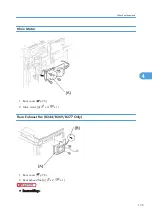
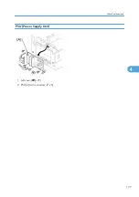
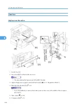
Page 139: ...PSU Power Supply Unit 1 Left cover p 79 2 PSU A All connectors x 6 Other Replacements 137 4 ...

Page 140: ...opmost part of the BICU bracket 3 High voltage power supply board with the bracket p 115 Registration Clutch 4 BICU with the bracket C x 6 If you have difficulty to remove the bracket remove the screw at the middle of the crosspiece see step 6 5 Main motor p 135 6 Crosspiece D x 3 4 Replacement and Adjustment 138 4 ...

Page 141: ... the PCU 9 Ground plate E x 2 10 Gearbox F x 5 1 belt Do not change the position of the spring G and make sure that the bushing H on the PCU drive shaft is in the correct position you when you reassemble You can adjust its position by rotating the gear I seen from the opening of the gearbox Other Replacements 139 4 ...

Page 142: ...ers show both on the gearbox and on the front exposed surface of each gear If the gears fall out start by finding gear number 1 and installing it onto location number 1 setting it into place so that the side with the printed number stays visible Then install the remaining gears 2 to 12 in the same way 4 Replacement and Adjustment 140 4 ...

Page 143: ...ach paper tray before you start these adjustments Use the Trimming Area Pattern SP 5902 No 10 to print the test pattern for the printing adjustments below Set SP 5902 to 0 again after you complete these printing adjustments Registration Leading Edge Side to Side 1 Check the leading edge registration for each paper feed station and adjust each of these registrations using SP 1001 2 Check the side t...

Page 144: ...02 4 Duplex SP 1002 5 A Leading Edge Registration B Side to side Registration Blank Margin If the leading edge or side to side registration cannot be adjusted to within the specification then adjust the leading edge blank margin or the left side blank margin 1 Check the trailing edge and right side edge blank margins and adjust them using the following SP modes 4 Replacement and Adjustment 142 4 ...

Page 145: ...tion 1 Print the single dot grid pattern SP 5902 1 2 Check the magnification the grid size should be 2 7 x 2 7 mm and if necessary use SP 2998 to adjust it The specification is 100 1 Scanning Before doing the following scanner adjustments check and adjust the printing leading edge and side to side registrations and the printing blank margins as described above Use an A3 test chart to perform the f...

Page 146: ...ecification Leading edge SP 4010 2 1 5 mm Side to side SP 4011 A Leading edge registration B Side to side registration Magnification A Main scan magnification B Sub scan magnification Main Scan Magnification 1 Place the A3 test chart on the exposure glass and make a copy from one of the feed stations 2 Check the magnification ratio If necessary adjust the magnification using the following SP mode ...

Page 147: ... do any of the following After you replace the standard white plate After you replace the NVRAM on the BICU But note that you do not need to carry out this adjustment if you have replaced the BICU itself but retained the previous NVRAM board by moving it over onto the new BICU After you perform a memory all clear SP 5801 2 Procedure 1 Place 10 sheets of new A4 LTR paper sideways LEF or new A3 DLT ...

Page 148: ... side registration SP 6006 1 Leading edge registration SP 6006 2 Blank margin for the trailing edge SP 6006 3 Side to side registration Duplex back side SP 6006 4 Sub scan Magnification A Sub scan magnification Make a temporary test chart as shown above with A3 11 x 17 paper 1 Place the temporary test chart on the ADF and make a copy from one of the feed stations 2 Check the registration and if ne...

Page 149: ... The SP Mode includes the programs that are necessary for standard maintenance work SSP Mode Special SP Mode The SSP Mode includes SP Mode programs and some special programs You need some extra knowledge to manipulate these special programs For details consult your supervisor Starting SP Mode For details about starting SP mode ask your supervisor Starting SSP Mode For details about starting SP mod...

Page 150: ...egative minus values press the period asterisk key 3 To validate the value press the OK key To cancel the value press the cancel key E Activating Copy Mode You can activate the copy mode while the SP mode is running When you do so the copier outputs images or patterns that help you adjust the SP mode program 1 Press the key The copy mode is activated 2 Specify copy settings and press the OK key 3 ...

Page 151: ...SP Mode Tables See Appendices for the SP Mode Tables SP Mode Tables 149 5 ...

Page 152: ...tration and Magnification To adjust the registration and magnification you need to use several service programs The chart shows an example of the procedure to adjust the machine in the basic configuration 5 System Maintenance 150 5 ...

Page 153: ...SP 2221 1 Vsg VG in the display Vsg 2 5V or Vsg Vsp 1 00V ID sensor defective ID sensor dirty Drum not charged SP 2221 2 Vsp VP in the display Vsp 2 5V or Vsg Vsp 1 00V Toner density very low ID sensor pattern not created SP 2221 3 Power PW in the display Vsg 3 5V when maximum power 979 is applied ID sensor defective ID sensor dirty Drum not get charged Power source for the ID sensor light SP 2221...

Page 154: ... digits The first digit indicates the output of L2 the second digit L1 the third digit W2 and the fourth digit W1 The other four digits from the fifth through the eighth are always 0000 In Example 1 the APS sensors L2 and L1 detect paper W2 and W1 do not In Example 2 APS sensors W2 and W1 detect paper L2 and L1 do not The paper size and its orientation is based on the outputs of these four APS sen...

Page 155: ... engine data is cleared by SP 5998 1 while the data in the controller NVRAM controller data is cleared by SP 5801 xxx see exceptions 002 Main Motor Reverse 003 Quenching Lamp Machine Data NVRAM Cleared by Remarks Basic All data BICU SP 5801 2 GDI Engine data BICU SP 5998 1 Any data other than controller data Controller data Controller SP 5801 xxx SCS IMH MCS Copier application Printer application ...

Page 156: ...C Print SP 5990 Be sure to print out all the lists You have to manually change the SP settings if the NVRAM data upload ends abnormally 3 Select SP 5801 2 4 Press the OK key 5 Select Execute The messages Execute followed by Cancel and Execute shows 6 Select Execute 7 When the program has ended normally the message Completed shows If the program has ended abnormally an error message shows 8 Press t...

Page 157: ...nd the paper path Input Check SP 5803 Conducting an Input Check 1 Select SP 5803 2 Select the number see the table below corresponding to the component 3 Select Execute The copy mode is activated 4 The sign 01H or 00H show see the table below Input Check Table Num Sensor Switch 01H 00H 001 Safety SW Open Closed 002 Safety SW LD 5V Open Closed 003 Right Cover SW Open Closed 004 Right Low Cover SW O...

Page 158: ...er detected Not detected 021 BK Lower Paper End S Paper detected Not detected 022 BK Up P Size SW 1 023 BK Low P Size SW 1 024 BK Up P Height S 2 025 BK Low P Height S 2 026 BK Upper Lift S At upper limit Not at upper limit 028 BK type 3 030 Duplex Installed Installed Not installed 031 Lower Lift S At upper limit Not at upper limit 032 Main M Lock Locked Not locked 033 Polygon M Lock Locked Not lo...

Page 159: ...r S Open Closed 046 1 bin Installed Installed Not installed 047 1 bin Exit S Paper detected Not detected 048 1 bin Paper S Paper detected Not detected 049 1 bin Tray S Open Closed 050 Fan Motor Lock High speed Not high speed 051 2 Tray BK Install Installed Not installed 053 HP Sensor Detected Not detected 054 Duplex Fan M Lock Locked Not locked 1 Paper Size Copier 00 01 02 03 04 05 06 07 Europe No...

Page 160: ... China B6 SEF B6 SEF A5 SEF A5 SEF B5 SEF A4 SEF B4 SEF A3 SEF 2 Paper Amount 10 Near end 11 About 25 00 About 75 00 About 100 3 Available Paper Feed Unit 00 None 20 2 tray paper feed unit 30 1 tray paper feed unit Output Check SP 5804 Conducting an Output Check To prevent mechanical or electrical damage do not keep an electrical component on for a long time 1 Select SP 5804 2 Select the number se...

Page 161: ...Supply Motor Forward 005 Fan Motor High 006 Fan Motor Low 007 Registration Clutch 008 By pass Feed Clutch 009 Upper Feed Clutch 010 Lower Feed Clutch 011 BK Low Lift Motor Up 012 BK Low Lift Motor Down 013 Relay Clutch 014 BK Relay Clutch 015 BK Upper Feed Clutch 016 BK Lower Feed Clutch 017 BK Lift Motor 018 BK Up Lift Motor Up 019 BK Up Lift Motor Down 020 Duplex Inv Motor Reverse 021 Duplex Inv...

Page 162: ...enoid 035 1 bin Gate Solenoid 036 1 bin Tray Motor 037 1 bin Tray Motor Hold 038 Fusing Solenoid 040 Duplex Fan Motor High 041 Duplex Fan Motor Low Serial Number Input SP 5811 Specifying Characters SP 5811 1 specifies the serial number For the basic machine the machine without the optional controller you use the numeric keypad For the GDI machine the machine with the optional controller you use th...

Page 163: ...ad Download SP 5824 5825 This procedure is for the basic machine only Makesurethatyouturnoffthemainswitchbeforeinsertingorremovingaflashmemorycard Installing or removing a flash memory card while the main switch is on may damage the BICU or memory Overview You can copy the data from the NVRAM to a flash memory card NVRAM Upload or from a flash memory card to the NVRAM NVRAM download SP 5824 1 NVRA...

Page 164: ... settings to the flash memory card This takes about 20 seconds If uploading fails an error message appears If an error message appears retry the upload procedure 7 Turn off the main switch 8 Remove the memory card NVRAM Download SP 5825 1 SP 5825 1 copies the data from the flash memory card to the NVRAM The following data is NOT copied the data in the NVRAM remains unchanged SP 8221 1 ADF Original...

Page 165: ...nd Ifdownloadingfails anerrormessageappears Ifanerrormessage appears retry the download procedure 7 Turn off the main switch 8 Remove the memory card Test Pattern Print SP 5902 1 Executing Test Pattern Printing 1 Specify the pattern number and press the OK key 2 Press the copy start key The copy mode is activated 3 Specify copy settings and press the key 4 To return to the SP mode press the key Te...

Page 166: ...ayscales With White Lines Horizontal 17 Grayscales with White Lines Vertical 18 Grayscales with White Lines Vertical Horizontal Test Patterns Using IPU No Pattern 30 Vertical Lines Single Dot 31 Horizontal Lines Single Dot 32 Vertical Lines Double Dot 33 Horizontal Lines Double Dot 34 Isolated Four Dots 35 Grid Pattern Double Dot 36 Black Band Vertical 1024 Dots 37 Grayscales Horizontal 512 Dots 3...

Page 167: ... Grades 49 Trimming Area A4 Test Patterns Using SBU No Pattern 51 Grid Pattern double dot 52 Gray scale 1 256 grades 53 Gray scale 2 256 grades Paper Jam Counters SP 7504 The table lists the menu numbers the last three digits of SP 7504 XXX and the paper jam timings and locations Code 001 Paper jam occurs at power on 010 Paper does not reach the registration sensor from a paper tray 011 Paper does...

Page 168: ...er is caught at the exit sensor previous page 121 Paper does not reach the exit sensor 122 Paper is caught at the exit sensor 123 Paper does not reach the duplex inverter sensor from the registration roller 125 Paper is caught at the duplex inverter sensor 126 Paper does not reach the duplex entrance sensor 127 Paper is caught at the duplex entrance sensor 128 Paper does not reach the duplex exit ...

Page 169: ... settings and press the key The machine status lists is output GDI machine The machine status list is output 4 To return to the SP mode press the key Original Jam History Display SP 7508 Viewing the Copy Jam History You can view the information on the most recent 10 events The information on older events is deleted automatically The information on jam history is saved in the NVRAM 1 Select SP 7508...

Page 170: ...at the original reverse sensor ADF APS Sensor Output Display SP 6901 Sensor Positions Large to Small W1 1 0 0 1 W2 0 0 1 1 Reading Data W1 W2 L1 L2 Paper Size EU AA 0 0 0 0 B5 LEF 0 0 1 1 B4 0 1 0 0 A5 LEF 0 1 1 0 A4 SEF 1 1 1 1 81 2 x 13 1 0 0 0 A4 LEF 1 0 1 1 A3 5 System Maintenance 168 5 ...

Page 171: ...1 1 0 0 A5 SEF 1 1 1 0 B5 SEF 1 Detected Using SP Modes 169 5 ...

Page 172: ... following firmware programs Firmware Type SP Mode Version Engine BICU 7801 2 B2685581 Ver 0 04 EXP GDI Printer Scanner 7801 15 A 001 Engine BICU Firmware Update Procedure 1 Turn the main switch off 2 Remove the card cover B 1 rivet 3 Insert the flash memory card A 5 System Maintenance 170 5 ...

Page 173: ... Make sure the message End Sum shows This message indicates that the program has ended normally 8 Turn off the main switch 9 Remove the flash memory card 10 Replace the card cover B 1 rivet 11 Turn the main switch on 12 Check the operation GDI Printer Scanner Update Procedure This section illustrates how to update the firmware of the GDI machine the machine with the optional controller box Firmwar...

Page 174: ...re high humidity or exposure to direct sunlight Always handle SD cards with care to avoid bending or scratching them Never drop an SD card or expose it to other shock or vibration Keep the following points in mind while you are using the firmware update software Upload means to send data from the machine to the SD card and download means to send data from the SD card to the machine Before starting...

Page 175: ...2 Unplug the DF cable A if installed 3 Rear cover B x 6 4 Remove the SD slot cover x 1 5 Insert the SD card in the SD slot B Firmware Update Procedure 173 5 ...

Page 176: ...6 Remove the controller box cover A x 7 7 Move the switch of the SW2 from OFF lower to ON upper 8 Turn on the main switch 5 System Maintenance 174 5 ...

Page 177: ...t or switch of the SW2 on the controller board is set to ON 10 Press the OK button A 11 Press the EXECUTE button A Do not turn the machine off while the message Updating xx shows This message indicates the program is running Make sure the message Completed shows This message indicates the program has successfully ended 12 Turn off the main switch Firmware Update Procedure 175 5 ...

Page 178: ...oad Failed Turn off on the main SW message is displayed on the LCD 14 Remove the SD card from the SD slot 15 Reassemble the controller box cover x 7 16 Reassemble the rear cover x 6 17 Reassemble the SD slot cover A x 1 18 Turn on the main power switch If Program Download Download Failed Turn off on the main SW message is displayed on the LCD check the SW2 on the controller is set to OFF lower 5 S...

Page 179: ...ction the SC can be reset by turning the main power switch off and on Turn the main power switch off and on C Themainmachinecanbeoperatedasusual excluding the unit related to the service call Turn the main power switch off and on D The SC history is updated The machine can be operated as usual The SC will not be displayed Only the SC history is updated If the problem concerns electrical circuit bo...

Page 180: ...B Scanner home position error 1 The scanner home position sensor does not detect the off condition during initialization or copying Scanner home position sensor defective Scanner drive motor defective Scanner home position sensor connector defective Scanner drive motor connector defective BICU board defective 121 B Scanner home position error 2 The scanner home position sensor does not detect the ...

Page 181: ... the BICU board and the SBU is damaged BICU board defective SBU defective 145 D Automatic SBU adjustment error During the automatic SBU adjustment the machine detects that the white level read from the whiteplateorpaperisoutofrange SP4015 Exposure lamp defective Dirty white plate Incorrect position or width of white plate scanning SP4015 BICU board defective SBU board defective 193 B Image transfe...

Page 182: ...ve 321 C No laser writing signal F GATE error The laser writing signal F GATE fails to turn Low after the laser crosses 5 mm on the drum surface from the laser writing start position BICU board defective The fax controller or printer controller has a poor connection Fax controller or printer controller defective 322 B Laser synchronization error The main scan synchronization detector board cannot ...

Page 183: ...not detected High voltage supply board defective Poor connection of the PCU Transfer separation unit set incorrectly Transfer roller damaged 402 B Transfer roller leak error 2 A current leak signal for the transfer roller is detected A current feedback signal for the transfer roller is not detected High voltage supply board defective Poor connection of the PCU Transfer separation unit set incorrec...

Page 184: ... 504 C Tray 4 lift motor malfunction optional two tray paper tray unit Thepaperliftsensorfailstoactivate twice continuously after the tray lift motor has been on for 18 seconds Paper lift sensor defective Tray lift motor defective Too much load on the drive mechanism Poor tray lift motor connection 506 C Paper feed motor lock optional paper tray units A motor lock signal is not detected for more t...

Page 185: ... by the fusing temperature monitor circuit Fusing thermistor defective Power supply board defective 545 A Fusing lamp overheat error center After the fusing temperature reaches the target temperature the fusing lamp does not turn off for 12 consecutive seconds Fusing thermistor defective or out of position Power supply board defective 546 A Unstable fusing temperature center The fusing temperature...

Page 186: ...etected by the thermistor Fusing thermistor defective Power supply board defective 555 A Fusing lamp overheat error rear After the fusing temperature reaches the target temperature the fusing lamp does not turn off for 20 consecutive seconds Fusing thermistor defective or out of position Power supply board defective 556 A Unstable fusing temperature rear The fusing temperature varies 50 C or more ...

Page 187: ...nd ADF main board DF connector ADF main board defective BICU defective 621 B ADF connection error An incorrect ADF an ADF for some other copier is detected for Basic and GDI machines An ADF including the correct ADF is installed while the copier is in the energy saver mode for GDI machine only ADF incorrect The ADF for B039 B040 B043 or B121 B122 B123 is installed on a B244 B268 B269 B276 B277 The...

Page 188: ...between the printer part of the controller board and BICU The connector is abnormal between the controller board and the BICU board 694 Controller board communication abnormal Communication error between the scanner part of the controller board and BICU The connector is abnormal between the controller board and the BICU board 760 B ADF gate abnormal 1 The ADF Gate signal line between the ADF main ...

Page 189: ...mission end command within the specified time Controller board defective 818 B Watchdog error The CPU does not access the watchdog register within a certain time Controller board defective Software malfunction download controller firmware again 819 B Kernel mismatch error Software bug Download controller firmware again 820 B Self Diagnostic Error CPU The central processing unit returned an error d...

Page 190: ...er board 827 B Self diagnostic Error RAM The resident RAM returned a verify error during the self diagnostic test Download controller firmware again 828 B Self diagnostic Error ROM The resident read only memory returned an error during the self diagnostic test Controller board defective Download controller firmware again 829 C Self diagnostic Error Optional RAM The optional RAM returned an error d...

Page 191: ...920 C Printer error A fatal error is detected in the printer application program Printer application program defective Hardware configuration incorrect including memory shortage 921 C Printer font error Necessary font files are not found Font file not installed 928 B Memory error The machine detects a discrepancy in the write read data during its write read test done at power off on and at recover...

Page 192: ...in the NVRAM write read data when attempting to save actual data to the NVRAM i e during actual use NVRAM defective Poor connection between BICU and NVRAM NVRAM is not connected BICU defective 982 B Localization error The localization settings in the nonvolatile ROM and RAM are different SP5807 First machine start after the NVRAM is replaced Incorrect localization setting NVRAM defective 984 B Pri...

Page 193: ...he software No operation required This SC code does not appear on the panel and is only logged 992 B Unexpected Software Error Software encountered an unexpected operation not defined under any SC code Software defective AnerrorundetectablebyanyotherSCcode occurred 997 B Application function selection error The application selected by a key press on operation panel does not start or ends abnormall...

Page 194: ...efective Loss of power during downloading Important Notes About SC999 Primarily intended for operating in the download mode logging is not performed with SC999 If the machine loses power while downloading or if for some other reason the download does not end normally this could damage the controller board or the PCB targeted for the download and prevent subsequent downloading If this problem occur...

Page 195: ...ears even if there is no paper at the sensor Upper Paper End 114 2 BICU Open The Paper End indicator lights when the 1st paper tray is selected even if there is paper in the tray Shorted The Paper End indicator does not light when the 1st paper tray is selected even if there is no paper in the tray The Paper Jam message will appear whenever a copy is made from the 1st paper tray Vertical Transport...

Page 196: ...oes not light when the bypass tray is selected even if there is no paper in the tray The Paper Jam message will appear whenever a copy is made from the bypass tray Exit 124 2 BICU Open The Paper Jam message will appear whenever a copy is made paper has not reached the sensor Shorted The Paper Jam message appears even if there is no paper at the sensor Toner Density 125 3 BICU Open SC390 is display...

Page 197: ...made paper has not reached the sensor Shorted The Paper Jam message appears even if there is no paper at the sensor Duplex Inverter 220 6 DCB Open The Paper Jam message will appear whenever a duplex copy is made paper has not reached the sensor Shorted The Paper Jam message appears even if there is no paper at the sensor SC392isactivatedwhentheCPUdetectsanIDsensorerrorduringdeveloperinitialization...

Page 198: ...r Size 136 1 2 4 5 BICU Open The CPU misdetects or is not able to detect the size of the paper set in the bypass tray causing possible misfeeds when feeding from this tray Right Door 124 5 BICU Open The Cover Open indicator is lit even if the right door is closed Shorted The Cover Open indicator is not lit even if the right door is open Front Right Cover 130 1 BICU Open The Cover Open indicator is...

Page 199: ...following table are on the power supply board Fuse Rating 120 V 220 240 V FU1 15A 125V 8A 250V FU2 5A 125V 2 5A 250V FU3 1A 250V 1A 250V FU4 4A 250V 4A 250V FU5 4A 250V 4A 250V FU6 4A 250V 4A 250V FU7 4A 250V 4A 250V Blown Fuse Conditions 197 6 ...

Page 200: ...LED Display BICU Number Function LED 1 Monitors the 5 V line for the CPU and the surrounding circuit Usually this LED is blinking 6 Troubleshooting 198 6 ...

Page 201: ...modes of the basic machine the machine without the optional controller Overview The machine has two energy saver modes the Low Power Mode and the Night Off Mode The table lists the status of several components Operation panel Engine Exhaust fan Operating Mode On On On Low Power Mode Off On Off Night Off Mode Off Off Off 199 7 ...

Page 202: ...he user ends all manual operations Note that the Auto Off Timer does not wait for the Energy Saver Timer Therefore if the user specifies a smaller value in the Energy Saver Timer the Auto Off Timer expires earlier than the Energy Saver Timer In a case like this the Low Power Mode is not activated Instead the engine controller starts the Night Off Mode when the Auto Off Timer expires Specified valu...

Page 203: ...Low Power Mode Off On Off Transit Mode Off On Off Night Off Mode Off Off Off The Operating Mode here refers to all the modes or status other than the Low Power Mode and Night Off Mode Actual power consumption during the Operating Mode depends on job status and environmental conditions The SRAM is alive and backs up the engine controller AOF When AOF is off the engine controller is unable to start ...

Page 204: ... Function Priority The default application program starts when the System Auto Reset Timer expires User Tools System Settings Timer Settings System Auto Reset Timer Recovery Any of the following operations brings the machine back to the Operating Mode The power switch is pressed Originals are set on the document feeder The platen cover or document feeder is opened The controller receives a job ove...

Page 205: ... amount of paper used This means that less energy overall is used for paper production which improves the environment 1 Duplex Reduce paper volume in half 2 Combine mode Reduce paper volume in half 3 Duplex Combine Using both features together can further reduce paper volume by 3 4 Paper Save 203 7 ...

Page 206: ...e original the total counter goes up by 3 The duplex counter counts pages that have images on both sides For one duplex page the duplex counter goes up by 1 For a duplex job of a three page original the duplex counter will only increase by 1 even though two sheets are used Recommendation Please explain the above features to the customers so that they can reduce their paper usage 7 Energy Saving 20...

Page 207: ...Model K C3 5L Machine Code B244 B276 B277 B268 B269 Appendices 3 December 2010 ...

Page 208: ......

Page 209: ...ptional Equipment 13 ARDF 13 ADF 14 One Tray Paper Tray Unit 14 Two Tray Paper Tray Unit 15 One Bin Tray 16 2 Appendix Preventive Maintenance PM Tables 17 3 Appendix SP Mode Tables SP Mode Tables 21 SP1 XXX Feed 21 SP2 XXX Drum 25 SP4 XXX Scanner 31 SP5 XXX Mode 38 SP6 XXX Peripherals 41 SP7 XXX Data Log 42 SP8 XXX History 48 SP9 XXX Etc 53 1 ...

Page 210: ...2 ...

Page 211: ...he bypass tray Width 90 297 mm 3 55 11 69 Length 148 600 mm 5 83 23 62 NOTE Physically the by pass tray can handle the following size but this size is not recognized by the application software Width 305 mm Length 1 260 mm Copy Paper Weight Paper Tray 60 90 g m2 16 24 lb Bypass 52 162 g m2 14 43 lb Reproduction Ratios 3 enlargement and 4 reduction A4 A3 Version LT DLT Version Enlargement 200 141 1...

Page 212: ... Full system Not above 40 dB A Operating Mainframe only Not above 62 dB A Operating Full System Not above 66 dB A The above measurements were made in accordance with ISO 7779 Measurements were taken from the normal position of the operator Dimensions W x D x H B245 B276 B268 550 x 568 x 420 mm 21 7 x 22 4 x 16 5 B269 B277 587 x 568 x 558 mm 23 1 x 22 4 x 23 0 Measurement Conditions 1 With bypass f...

Page 213: ... than 10 seconds at 20 C 68 F GDI model Less than 10 seconds at 20 C 68 F First Copy Time Not more than 6 5 seconds Measurement Conditions 1 From the ready state with the polygonal mirror motor operating 2 A4 LT copying 3 Not APS mode 4 100 size 5 Paper feed from the upper tray Copy Number Input Numeric keypad 1 to 99 increment decrement Manual Image Density 5 steps Automatic Reset Default is 60 s...

Page 214: ...reverse document feeder B269 B277 only Paper tray unit 1 tray Paper tray unit 2 trays 1 bin tray B269 B277 only Tray heater B269 B277 only Optics anti condensation heater GDI controller board Toner Yield 9k copies A4 LEF 6 full black 1 to 2 copying normal text mode Copy Tray Capacity 250 sheets Memory Basic Model 16 MB BICU GDI Model 16 MB BICU 32 MB Controller GDI NIC Model 16 MB BICU 64 MB Contr...

Page 215: ...mm A4 LT A4 LT X X B5 SEF 182 x 257 mm O O O X B5 LEF 257 x 182 mm O O X X A5 SEF 148 x 210 mm O O O X A5 LEF 210 x 148 mm O O Sa X B6 SEF 128 x 182 mm O O O O B6 LEF 182 x 128 mm O O O O 8K SEF 267 x 390 mm O O O O 16K SEF 195 x 267 mm O O O O 16K LEF 267 x 195 mm O O O O DLT SEF 11 x 17 X X O O SEF 11 x 15 O O O O LG SEF 81 2 x 14 X X O O LT SEF 81 2 x 11 X X A4 LT A4 LT LT LEF 11 x 81 2 X X A4 ...

Page 216: ...arto LEF 10 x 8 O O O O Key X Detected O Not detected F Detected as F 81 2 x 13 S Detected as specified A4 LT Detected as A4 or LT as specified aWhen the settings of SP 4305 1 is 1 A4 LT the settings of SP 4303 is invalidated A5 LEF is not detected China Korea Paper Size W x L China Korea China Korea localized Platen ADF Platenb ADFc A3 SEF 297 x 420 mm X X X O B4 SEF 257 x 364 mm X X O O A4 SEF 2...

Page 217: ...8K SEF 267 x 390 mm O O X X 16K SEF 195 x 267 mm O O X X 16K LEF 267 x 195 mm O O X X DLT SEF 11 x 17 O O O O SEF 11 x 15 O O O O LG SEF 81 2 x 14 O O O O LT SEF 81 2 x 11 A4 LT A4 LT O O LT LEF 11 x 81 2 A4 LT A4 LT O O HLT SEF 51 2 x 81 2 O O O O HLT LEF 81 2 x 51 2 O O O O F GL F4 SEF 8 x 13 O F O F Foolscap SEF 81 2 x 13 O F O F Folio SEF 81 4 x 13 O F O F USB4 SEF 10 x 14 O O O O Eng Quarto S...

Page 218: ...nd Exit Main Frame Duplex Paper Size W x L Main frame tray Duplex China Korea North America Europe Asia Taiwan A3 SEF 297 x 420 mm X M X X X A3 LEF 420 x 297 mm O O O O O B4 SEF 257 x 364 mm X M M M X B4 LEF 364 x 257 mm O O O O O A4 SEF 210 x 297 mm X M X X X A4 LEF 297 x 210 mm X X X X X B5 SEF 182 x 257 mm M M M M X B5 LEF 257 x 182 mm X M M M X A5 SEF 148 x 210 mm O O O O X A5 LEF 210 x 148 mm...

Page 219: ...x 81 2 O O O O O Gov LG SEF 81 4 x 14 M M M M X Gov LG LEF 14 x 81 4 O O O O O LT SEF 81 2 x 11 M X M M X LT LEF 11 x 81 2 M X X X X HLT SEF 51 2 x 81 2 O O O O O HLT LEF 81 2 x 51 2 M M M M O Executive SEF 71 4 x 101 2 M M M M X Executive LEF 101 2 x 71 4 M M M M X F SEF 8 x 13 M M M M X F LEF 13 x 8 O O O O O Foolscap SEF 81 2 x 13 M X X X X Foolscap LEF 13 x 81 2 O O O O O Folio SEF 81 4 x 13 M...

Page 220: ...62 x 229 mm O O O O O C6 Env SEF 114 x 162 mm O O O O O DL Env SEF 110 x 220 mm O O O O O Com10 SEF 41 8 x 91 2 O O O O O Monarch SEF 37 8 x 71 2 O O O O O Custom O O O O O Key X Detected Main frame tray Processed Duplex O Not detected Main frame tray Not processed Duplex M Selected manually K Specified from the key pad Custom W 90 to 297 mm L 148 to 600 mm 1 Appendix Specifications 12 1 ...

Page 221: ... mm Original Weight Single sided mode 40 128 g m2 10 34 lb Double sided mode 52 105 g m2 14 28 lb Table Capacity 50 sheets 80 g m2 70 kg Original Standard Position Center Separation FRR Original Transport Roller transport Original Feed Order From the top original Reproduction Range 50 to 200 Sub scan direction only Power Source 24 and 5 Vdc from the copier Power Consumption 50 W Dimensions W x D x...

Page 222: ... Original Transport Roller transport Original Feed Order From the top original Reproduction Range 50 200 Power Source 24 and 5 Vdc from the main frame Power Consumption 25 W Dimensions W x D x H 550 mm x 470 mm x 90 mm Weight Not above 7 kg 15 lb One Tray Paper Tray Unit Paper Size A5 to A3 51 2 x 81 2 SEF to 11 x 17 Paper Weight 60 105 g m2 16 28 lb Tray Capacity 500 sheets 80 g m2 20 lb x 1 tray...

Page 223: ...A5 to A3 51 2 x 81 2 SEF to 11 x 17 Paper Weight 60 105 g m2 16 28 lb Tray Capacity 500 sheets 80 g m2 20 lb x 2 trays Paper Feed System Feed roller and friction pad Paper Height Detection 4 steps 100 70 30 Near end Power Source 24 Vdc and 5Vdc from the copier printer 120 Vac 120 V version from the copier printer when the optional tray heater is installed 220 240 Vac 230 V version from the copier ...

Page 224: ...eight 60 105 g m 16 28 lb Tray Capacity 100 sheets A4 LEF 80 g m2 20 lb Power Source 5 VDC 24 VDC from the copier Power Consumption Max 20 W Weight 1 55 kg Base unit 1 1 kg Tray 0 45 kg Size W x D x H 461 mm x 478 mm x 104 mm 508 mm x 478 mm x 104 mm when tray extended 1 Appendix Specifications 16 1 ...

Page 225: ...tics EM 60k 120k AN NOTE Reflector C Optics cloth 1st mirror C C Optics cloth 2nd mirror C C Optics cloth 3rd mirror C C Optics cloth Scanner guide rails C Do not use alcohol Platen cover I C Replace the platen sheet if necessary Blower brush or alcohol Exposure glass C C Blower brush or alcohol Toner shield glass C Blower brush APS sensors C Blower brush Drum Area EM 60k 120k AN NOTE PCU I Drum R...

Page 226: ...per feed roller bypass tray C C Clean with water or alcohol Friction pad bypass tray C C Clean with water or alcohol Bottom plate pad by pass tray C C Clean with water or alcohol Registration rollers C C Clean with water or alcohol Relay rollers C C Clean with water or alcohol Paper feed guides C C Clean with water or alcohol Paper dust Mylar C C Clean with water or alcohol Fusing Unit EM 60k 120k...

Page 227: ...r or alcohol Stamp R Replace when necessary White plate C Clean with water or alcohol DF exposure glass C Clean with water or alcohol Platen cover C Clean with water or alcohol Paper Tray Unit 60k 120k AN NOTE Paper feed rollers R C Dry or damp cloth Bottom plate pads C C Dry cloth Paper feed guides C C Clean with water or alcohol Friction pads R C Dry or damp cloth Relay clutch B384 only I Feed c...

Page 228: ...2 Appendix Preventive Maintenance 20 2 ...

Page 229: ...ng Edge Registration Adjusts the printing leading edge registration from paper trays 1001 1 All Trays 9 0 to 9 0 0 0 0 1 mm step Copy Adjustments Printing Scanning 1001 2 By pass 1001 3 Duplex 1002 Side to Side Registration Adjusts the printing side to side registration from each paper feed station using the Trimming Area Pattern SP 5902 No 10 Adjustments are supported for all 4 possible feed tray...

Page 230: ...uplex 0 to 20 6 1 mm step 1007 Display By pass 1007 1 Display By pass Displays the by pass paper width switch output 1103 Fusing Idling This program decides the action of the Fusing Drive Release Mechanism When you select 1 the contact release control is disabled and the drive power is always transmitted to the fusing unit As a result the machine takes a longer time to warm up the fusing unit Use ...

Page 231: ... fusing temperature center 1106 2 Displays the fusing temperature end 1107 Fusing Soft Start Adjusts the number of zero cross cycles of the fusing lamp AC supply needed to bring the fusing lamp power to 100 while bringing the lamp up to the standby temperature or while copying Increase this value if the machine is experiencing sudden power dropouts Fusing Temperature Control 1107 1 Warm Up Soft St...

Page 232: ...equency as detected by the zero cross signal generator The displayed value is 1 5 the actual frequency 10 50 Hz 12 60 Hz 1903 Feed Clutch Boost Adjusts the amount of extra push that the feed clutch gives to the paper after the skew has been corrected at registration This feature helps the registration roller feed certain types of paper such as thick paper Increase the value if thick paper is jammi...

Page 233: ... 400 300 1 V step Adjusts the voltage applied to the charge roller when generating the Vsdp ID sensor pattern as part of charge roller voltage correction The actual charge roller voltage is obtained by adding this value to the value of SP 2001 1 2101 Erase Margin Adjustment 2101 1 Leading edge 0 0 to 9 0 2 0 0 1 mm step Copy Adjustments Printing Scanning Specification 2 1 5 mm Adjusts the leading ...

Page 234: ...e value of SP 2201 1 The setting affects ID sensor pattern density which in turn affects the toner supply 2213 Outputs after Near End 2213 1 0 50 pages 1 20 pages Sets the number of copy print pages that can be made after toner near end has been detected Reduce the number of pages if the user normally makes copies with a high image ratio 2214 Developer Initialization 2214 1 Initializes both the TD...

Page 235: ...nsfer roller when feeding from the by pass tray Use a high setting a if the user normally feeds relatively thick paper from the by pass tray or b ifwastetonerisre attractedfromthedrum whichcanoccurwhenusingtransparencies Image Transfer Current Timing 2301 3 Duplex 2 4 mA 1 2 mA 0 0 mA 1 2 mA 2 4 mA Adjusts the current applied to the transfer roller when carrying out a duplex job Use this SP if the...

Page 236: ...ced Toner Supply 2908 1 Forces the toner bottle to supply toner to the toner supply unit Press 1 to start The machine continues to supply toner until the toner concentration in the development unit reaches the standard level or for up to 2 minutes whichever comes first 2915 Polygon Mirror Motor Idling Time 2915 1 0 None 1 15 s 2 25 s Selects the polygon mirror motor idling time To increase the spe...

Page 237: ... 2925 Toner Supply Rate 2925 1 Adjusts the toner supply time for fixed toner supply mode This setting is effective only if SP 2921 is set to 2 or 3 0 to 7 0 t 200ms and settings are as follows 0 t 1 2t 2 4t 3 8t 4 12t 5 16t 6 on continuously 7 0 s Raising this value increases the toner supply motor ON time Set to a high value if the user tends to make many copies having high proportions of solid b...

Page 238: ... While the machine is recovering from an energy saver mode or while the machine starts the controller ignores the ID sensor signals if the fusing temperature is at the specified value or higher 2996 Transfer Roller Cleaning 2996 1 Selects whether the transfer roller is cleaned before each copy job Set this to 1 if dirty background is appearing on the reverse side of the first page of copy jobs Not...

Page 239: ...er 5 0 to 5 0 0 0 0 1 mm step 4010 1 Adjusts the leading edge registration for scanning in platen mode Copy Adjustments Printing Scanning The image moves toward the leading edge The image moves toward the trailing edge The specification is 2 1 5 mm 4011 Side to side Registration Scanner 4 2 to 4 2 0 0 0 1 mm step 4011 1 Adjusts the side to side registration for scanning in platen mode Copy Adjustm...

Page 240: ...can in the main scan direction The scan begins at the start position set above in SP 4015 1 and extends for the specified length The base value stored in the machine is 4 76 mm This SP setting specifies the offset from this base value 4301 Display APS Data 4301 1 Displays the status of the APS sensors and platen DF cover sensor ADF APS Sensor Output Display SP 6901 4303 APS Small Size Original 0 N...

Page 241: ...riginal sizes as LT SEF under the following conditions SP 4303 1 is Yes and SP 4305 1 is A4 LT 4428 Scan Auto Adjustment 4428 1 Performs the automatic scanner adjustment Use this SP mode after replacing the white plate 4901 SBU White Level Adjustment 4901 1 Black Display Error 0 Normal 1 Error Displays the return code of the black level adjustment When an error is detected SC143 or SC145 is genera...

Page 242: ...isplays how many times the white level adjustment is retried The value does not include the first execution of the white adjustment For example if the value is 2 this indicates that the white level adjustment has been executed three times The white level adjustment can be executed 20 times or less Therefore if the value is 20 this indicates that the white level adjustment has ended abnormally as d...

Page 243: ...1 step 4904 1 Adjusts the ADS lower limit 4905 ADS Level 0 All 1 One 4905 1 Checks the whole area 0 All or the area between 15 mm and 90 mm from the left edge 1 One to adjust the ADS level 4921 Image Adj Selection 4921 1 Image Adj Selection Copy 0 to 10 0 1 Selects which mode the settings from SP 4922 to SP 4932 and are used for 0 None 1 Text 1 2 Text 2 3 Photo 1 4 Photo 2 5 Photo 3 6 Special 1 7 ...

Page 244: ...l specified here The higher the setting level the less clear the image will become more texture removal This setting is only applied to the originals in SP 4921 4926 1 Texture Removal Copy 0 to 6 1 step 4926 3 Texture Removal Scanner 0 to 6 1 step 4927 Line Width Correction Adjusts the line width correction algorithm Positive settings produce thicker lines negative settings produce thinner lines T...

Page 245: ...step Adjust the clarity This setting is only applied to the originals in SP 4921 4932 1 Sharpness Low ID Copy 4941 White Line Erase 0 to 2 1 1 step 4941 1 Selects the white line erase level 0 None 1 Weak 2 Strong This setting is effective only Photo 1 Photo 3 Special 3 or Special 4 mode 0 White line erase is not used and white level correction is used instead This setting is applied regardless of ...

Page 246: ...y card Increment 12 MF key card Decrement 5113 1 Selects the corresponding key for installed devices such as coin lock 5120 Clr OP Count Remv 0 Yes 1 Standby only 2 No 5120 1 Determines under which conditions the copy job settings are reset when the key counter is removed With 0 the settings are cleared if the counter is removed at the end of a job or midway through a job With 1 they are only clea...

Page 247: ...utput Check Output Check SP 5804 5807 Area Selection 5807 1 Selects the display language group 1 Japan 2 North America 3 Europe 4 Taiwan 5 Asia 6 China 7 Korea SP 5807 1 is not cleared by SP 5801 2 Memory Clear 5810 SC Code Reset 5810 1 Resets all level A service call conditions such as fusing errors If the reset is successful the display shows Completed If the reset fails an error message shows 5...

Page 248: ... Download SP 5824 5825 5827 Program Download 5827 1 Downloads programs to the machine 5901 Printer Free Run 5901 1 Executes the free run Press ON to start press OFF to stop 5902 Test Pattern Print 5902 1 Test Pattern Print SP 5902 1 5907 Plug Play Setting 5907 1 Selects the brand name and production name for the Plug and Play function These names are registered in the NVRAM If the NVRAM becomes de...

Page 249: ... and its configuration 6006 1 ADF Adjustment StoS Front Regist 5 0 to 5 0 0 0 0 1 mm step Adjusts the side to side registration for the front side of the original for ADF mode Use the key to select or before entering the value 6006 2 ADF Adjustment Leading Regist 5 0 to 5 0 0 0 0 1 mm step Adjusts the leading edge registration for ADF mode Use the key to select or before entering the value 6006 3 ...

Page 250: ...6 7 is effective when you enable SP 6006 6 ADF Adjustment Original Curl Adj 6009 ADF Free Run 6009 1 Performs an ADF free run Press ON to start press OFF to stop 6010 Stamp Position Adjustment 10 to 10 0 1 mm step 6010 1 Adjusts the stamp position in the sub scan direction for the fax mode 6901 Display ADF APS 6901 1 Displays the status of the ADF original size sensors ADF APS Sensor Output Displa...

Page 251: ...umber of the paper jams classified by timing and location 7504 1 Counter Each P Jam At power on Paper jam occurs at power on 7504 10 Counter Each P Jam Off Regist NoFeed Paper does not reach the registration sensor from a paper tray 7504 11 Counter Each P Jam Off 1 Vertical SN Paper does not reach the relay sensor 7504 12 Counter Each P Jam On 1 Vertical SN Paper is caught at the relay sensor 7504...

Page 252: ...P Jam On Regist SN Paper is caught at the registration sensor 7504 120 Counter Each P Jam On Exit SN Paper is caught at the exit sensor previous page 7504 121 Counter Each P Jam Off Exit SN Paper does not reach the exit sensor 7504 122 Counter Each P Jam On Exit SN Paper is caught at the exit sensor 7504 123 Counter Each P Jam Off Dup Inverter Paper does not reach the duplex inverter sensor from t...

Page 253: ...05 210 Counter Each O Jam Off Regist SN The original does not reach the registration sensor 7505 211 Counter Each O Jam On Regist SN The original is caught at the registration sensor 7505 212 Counter Each O Jam Off Relay SN The original does not reach the exit sensor 7505 213 Counter Each O Jam On Relay SN The original is caught at the exit sensor 7505 214 Counter Each O Jam Off Inverter SN The or...

Page 254: ... 211 212 213 214 215 216 The codes correspond to the menus of SP 7505 For example the code 210 corresponds to SP 7505 210 and the code 211 corresponds to SP 7505 211 7801 Memory Version PN 7801 2 Memory Version BICU Displays the version of the BICU board 7801 5 Memory Version ADF Displays the P N and suffix of the ADF ROM 7801 15 Memory Version Printer Scanner Displays the P N and suffix of the Pr...

Page 255: ... error message is displayed If the customer forgets the keyoperatorcode Tospecifyanewkey operatorcode usetheUserTools SystemSettings Key Operator Tools Key Operator Code On Enter Key Operator Code 7832 Display Self Diag 7832 1 Displays the SC codes and the number of their occurrences Each number is in the range of 0 to 9999 7991 Dsply Info Count Displays the total operating time or the total numbe...

Page 256: ... copies Both sides are counted when the front and reverse sides of an original fed from the ADF are scanned 8195 S Total Scan PGS 0 9999999 0 1 sheet step 8195 1 Displays the total number of scanned originals Both sides are counted when the front and reverse sides of an original fed from the ADF are scanned 8201 T L Size Scan PGS 0 9999999 0 1 sheet step 8201 1 Displays the total number of scanned...

Page 257: ...99 0 1 sheet step 8381 1 Displays the print count of all application programs 8382 C Total Prt PGS 0 9999999 0 1 sheet step 8382 1 Displays the print count of the copier application program 8383 F Total Prt PGS 0 9999999 0 1 sheet step 8383 1 Displays the print count of the fax application program 8384 P Total Prt PGS 0 9999999 0 1 sheet step 8384 1 Displays the print count of the printer applicat...

Page 258: ...assified by combination duple type 8422 1 C PrtPGS Dup Comb Simplex Duplex Original Print 8422 2 C PrtPGS Dup Comb Duplex Duplex Original Print 8422 4 C PrtPGS Dup Comb Simplex Combine Original Print 8422 5 C PrtPGS Dup Comb Duplex Combine Original Print 8422 6 C PrtPGS Dup Comb 2 Original Print 8422 7 C PrtPGS Dup Comb 4 Original Print 8441 T PrtPGS Ppr Size 0 9999999 0 1 sheet step Displays the ...

Page 259: ...0 1 sheet step Displays the number of pages printed by the copier application program 8442 1 A3 8442 2 A4 8442 3 A5 8442 4 B4 8442 5 B5 8442 6 DLT 8442 7 LG 8442 8 LT 8442 9 HLT 8442 254 Other Standard 8442 255 Other Custom 8445 P PrtPGS Ppr Size 0 9999999 0 1 sheet step Displays the number of pages printed by the copier application program SP Mode Tables 51 3 ...

Page 260: ...sheet step Displays the total print count classified by paper source 8451 1 Bypass Tray 8451 2 Tray 1 8451 3 Tray 2 8451 4 Tray 3 8451 5 Tray 4 8461 T PrtPGS Ppr Type 0 9999999 0 1 sheet step Displays the total print count classified by paper size This is the total for all application programs 8461 1 Normal 8461 4 Thick 8461 7 OHP 8461 8 Other 3 Appendix SP Mode Tables 52 3 ...

Page 261: ...PGS Ppr Type 0 9999999 0 1 sheet step Displays the total print count classified by paper size This is the total for all application programs 8464 1 Normal 8464 4 Thick 8464 7 OHP 8464 8 Other 8522 C PrtPGS FIN Sort 0 9999999 0 1 sheet step 8522 1 Displays the total number of printing classified by paper size SP9 XXX Etc Not used in this machine SP Mode Tables 53 3 ...

Page 262: ...MEMO 54 ...

Page 263: ...MEMO 55 ...

Page 264: ...MEMO 56 EN ...

Reviews: