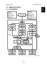
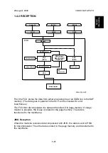
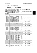
Ricoh B383, Service Manual
The Ricoh B383 is a versatile and reliable printer that offers exceptional printing quality. Need help troubleshooting or servicing your Ricoh B383? Download the free Service Manual from 88.208.23.73:8080 to access detailed instructions and diagrams to keep your printer running smoothly. Get your manual today!
Share
Download


Reviews:
No comments
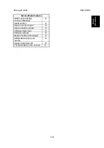
Related manuals for B383

FAXPHONE L190
Brand: Canon Pages: 28

FAXPHONE L190
Brand: Canon Pages: 100

FAXPHONE L80
Brand: Canon Pages: 124

FAXPHONE L80
Brand: Canon Pages: 203

FAXPHONE L100
Brand: Canon Pages: 28

MultiPASS L6000
Brand: Canon Pages: 39

MultiPASS 800
Brand: Canon Pages: 103

FAX-L280
Brand: Canon Pages: 24

MultiPASS C3500
Brand: Canon Pages: 47

PIXMA MX882 Series
Brand: Canon Pages: 80

FAX-L280
Brand: Canon Pages: 212

SmartBase PC1270D
Brand: Canon Pages: 88

FAX-B155
Brand: Canon Pages: 115

610
Brand: OKIFAX Pages: 147

C3000
Brand: Xerox Pages: 298

7042
Brand: Xerox Pages: 182

DP-180
Brand: Panasonic Pages: 65

Panafax UF-8000
Brand: Panasonic Pages: 187


