background image

A-4

Installation/Maintenance Area

184 ppm Printer and Container Stacker 1


( ? ? : mm)  

O

per

at

or

’s

 Si

de


Cont

ai

ner


St

acke

r 1


Pr

in

ter

 (

LB184A)


700 


(665) 


1200 

2565 


Ser

ver


Mai

nt

enanc

e Ar

ea 

Summary of Contents for Container Stacker

Page 1: ...Container Stacker Unpacking Setup Instructions 2007 Ricoh Corporation 5 Dedrick Place West Caldwell NJ 07006 January 2007 337641 006B ...

Page 2: ...using this product s documentation This document contains TrueType fonts from Monotype Imaging Inc Reproduction of these fonts is prohibited The software embedded in this product is based in part on the work of Independent JPEG Group The software embedded in this product uses software by CMU Copyright 1988 1989 by Carnegie Mellon University All rights reserved Permission to use copy modify distrib...

Page 3: ...i Revisions Revision Page No Contents Date A Original Release ECO 1554 October 2004 B Generic Version Add rev history page copyright page updated January 2007 ...

Page 4: ...iner Stacker 2 and Standard Finisher 1 26 Standard Finisher 70 ppm 1 26 Standard Finisher 92 184 ppm 1 29 Adjustment 1 33 Appendix A Installation Maintenance Area 70 92 ppm Printer and Container Stacker 1 A 1 70 92 ppm Printer High Capacity Hopper Container Stacker 1 and Container Stacker 2 A 2 70 92 ppm Printer High Capacity Hopper Container Stacker 2 and Standard Finisher A 3 184 ppm Printer and...

Page 5: ...ii Table of Contents ...
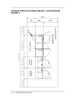
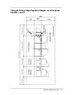
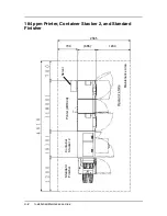
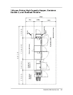
Page 6: ...ronmental Conditions The location where the Container Stacker is installed must meet the following environmental conditions Location of Leveling Bolts and Casters Install the leveling bolts and the casters to the Container Stackers 1 and 2 as follows ITEM CONDITION Temperature 10 to 32 C Humidity 20 to 80 RH non condensing Altitude 0 to 2 100 m ...

Page 7: ...path is clear of obstacles and high voltage areas or wires 5 Unplug the equipment before cleaning Unplug the Printer from the outlet before cleaning the inside of the Printer and label the power cord plug to prevent other persons from plugging it in while you are cleaning 6 Be sure to use the proper tools that are in good condition Use of worn or improper tools can cause injury TOOL APPLICATION Cu...

Page 8: ... clean dry location Do not place heavy objects 5 kg or more on top of the equipment Keep the equipment balanced when lifting with a forklift Use cushion materials to avoid damage Move the equipment at a speed of 300 mm sec 1 08 km h or slower Do not tilt the equipment more than 15 Slope on the path can be no more than 15 Do not allow condensation to form on the equipment Component Quantity Contain...

Page 9: ...1 4 Container Stacker Installation Instructions Unpacking 1 Using a cutter remove the V bandS from the shipping box and remove the cap V band Corner packing Plastic bag Tape V band P P band ...

Page 10: ...ieces 4 Peel off the adhesive tape and remove the plastic bag 5 Cut the tape from the 4 corners of the base packing and push down the side of the pallet to become an incline board Cap Spacer packing Pallet Shipping box Accessory box Upper packing Ramp Spacer box Upper packing Corner packing Base packing Corner packing Spacer packing Plastic bag Ramp Base packing Spacer box ...

Page 11: ...and place them at the bottom of the bolts under the plastic bag 7 Using an open end wrench raise the container stacker by rotating the leveling bolts 8 Remove the 4 pieces of base packing 9 Turn all the casters in the same direction 10 Install the ramps two on each side under the incline board Wood spacer Leveling bolt Down Up Ramp Incline Board ...

Page 12: ...Instructions 1 7 11 Raise the leveling bolts and remove the wood spacers 12 Carefully slide the container stacker onto the floor WARNING Do not attempt the following step without another person to help guide the stacker down the ramp ...

Page 13: ... 2 Open Front Cover L and peel off the adhesive tape Opening procedure for Front Cover L 1 Open Front Cover R 2 Using a Phillips screwdriver push cover release A in the direction of the arrow and open Front Cover L Tape Tape Tape Tape Tape Tape Tape Tape Front Cover L Front Cover L Front Cover L Container Stacker 1 or 2 Phillips Screwdriver Front Cover R Arrow A ...

Page 14: ...out of the lower basket 70 ppm only 4 Take the components out of the accessory box CP417 Assy Basket Screw Joint bracket L Basket small Joint bracket U Guide Plate L Guide Plate U Partition Hopper spacer ass y Details of screw 1 M3 x 8 2 pieces 2 M4 x 8 4 pieces 3 M4 x 12 6 pieces Accessory box ...

Page 15: ... ppm 1 Remove the 2000 sheet hopper 2 Turn the four leveling bolts until the casters do not touch the ground 3 Place a level on the Printer frame and adjust the leveling bolts until horizontal level is achieved Configuration Printer Container Stacker 1 Container Stacker 2 Standard Finisher DDP70e Standard Finisher DDP92 184 Reference Page 1 x x 8 2 x x x 8 16 3 x x x 8 21 4 x x x 8 24 Paper Guide ...

Page 16: ...Hopper 184 ppm 1 Open the Front Cover of the printer and loosen the two M4 screws 184 ppm only 2 Pull the upper part of the Front Lower Cover forward and unhook it by lifting and pulling forward M4 Screw 2000 Sheet Hopper Rear Engine Hook Front Cover M4 Screw Front Lower Cover ...

Page 17: ...city eliminator using the two M3x8 screws the front is lettered on the surface 3 Install the Guide Plate L using the two M3x8 screws with washers 4 Install Joint Bracket U and Joint Bracket L using the two M4x8 screws NOTE These installation instructions apply to the 70 92 and 184 ppm printers When installing a Container Stacker on a 184 ppm printer the word printer always refers to the Rear Engin...

Page 18: ...wo M4x8 screws 6 Remove the six M4 screws Unhook the lower hook of the Rear Cover and remove the Rear Cover by lifting and pulling it forward M4x8 Screw M4x8 Screw Joint Bracket L Joint Bracket U M3x8 Screw with Washer Guide Plate U Guide Plate L Static Electricity Eliminator M3x8 Screw Rear Cover M4 Screws ...

Page 19: ... M4 Screws and the Rear Cover 8 Attach Container Stacker 1 or 2 to the Printer and loosely install the screws NOTE Refer to page 5 for instructions on opening Front Cover L Rear Cover M4 Screws Container Stacker 1 or 2 M4x12 Screws Frame Projection Part M4x12 Screws ...

Page 20: ...ker frame projection is level with the Printer Paper Guide projection Adjust the horizontal level of the Container Stacker by placing a level on the stacker frame in the three locations shown below Tighten the screws completely 10 Verify the gap at A B C and D is nearly equal Stacker Frame Printer Paper Guide Level Front Cover L Projection Projection Same Height Leveling Bolts Connection Part Deta...

Page 21: ...llation Instructions 11 Open the L Paper Guide A of the Container Stacker and make sure that the SB Cover can be opened If the cover cannot be opened repeat steps 8 and 9 to readjust the Container Stacker L Paper Guide A SB Cover ...

Page 22: ...e connector of the CST AC cable Connection 2 on the figure below 16 Mount the CST FG cable coming from Container Stacker side on the Printer frame using an M4 screw Connection 3 on the following illustration 17 Install the CP417 P K on the CP P K holder and then install it and the board in the Printer 70 ppm only 18 Install the CP P K holder and OC P K ass y in the Printer 92 184 ppm only 19 Conne...

Page 23: ...the 4 pin white translucent connector of the Container Stacker Connection 5 on the following illustration 184ppm only NOTE Put the cable through opening A of the Printer On SW1 mounted on the CPXXX P K set switch No 5 to ON and set switch No 2 and No 8 to OFF Front Engine of 184 ppm printer J23 CST AC Cable CE AC Cable Connector 2 pin white Connector 2 pin PS Connection 1 and 2 Details 70 92 ppm C...

Page 24: ... 5 4 pin white CS Relay Cable Connection 5 4 pin white Disconnection 3 2 pin white Connection 4 20 pin black FNS IF Cable coming from Front Engine CST FG Cable CE AC Cable Connection 2 Connection 1 translucent 184 ppm J23 CST AC Cable CE AC Cable Connector 2 pin white Connector 2 pin PS Connection 1 and 2 Details ...

Page 25: ...1 20 Container Stacker Installation Instructions 22 Install the Rear Cover of the Printer and the Rear Cover of the Container Stacker M4 Screw ...

Page 26: ...rom the Printer 2 Attach the Guide Plate U with the Static Electricity eliminator using the two M3x8 Screws 3 Install Joint Bracket U and Joint Bracket L using the two M4x8 Screws NOTE Refer to page 9 for installation of the Printer and the Container Stacker 2 M4x8 Screw Guide Plate Container Stacker 2 Static Electricity Eliminator Joint Bracket U M3 Screw Joint Bracket L ...

Page 27: ... and remove the Rear Cover from Container Stacker 1 5 Attach Container Stacker 1 to Container Stacker 2 and loosely install the screws M4 Screws Rear Cover Container Stacker 1 Container Stacker 1 M4x12 Screws Frame Projection Part Container Stacker 2 M4x12 Screws M4x12 Screws ...

Page 28: ...vel with the Paper Guide projection Adjust the horizontal level of the Container Stacker by placing a level on the stacker frame in the three locations shown Tighten the screws completely 7 Verify the gap at A B C and D are nearly equal NOTE Refer to page 5 for instructions on opening Front Cover L Stacker Frame Stacker Paper Guide Level Front Cover L Projection Projection Same Height Leveling Bol...

Page 29: ...on 3 on the following illustration 11 Mount the CST FG cable coming from Container Stacker 1 on the frame of Container Stacker 2 using M4 Screw Connection 4 on the following illustration NOTE Put the cable through opening A of the Printer On SW1 mounted on the CPXXX P K set switch No 4 and No 5 to ON and set No 2 and No 8 to OFF Front Engine of 184 ppm Connection 2 2 pin white Connection 1 20 pin ...

Page 30: ... Installation Instructions 1 25 12 Install the Rear Covers of the Printer Container Stacker 1 and Container Stacker 2 Printer Rear Cover M4 Screws Container Stacker 2 Rear Cover M4 Screws Container Stacker 1 Rear Cover ...

Page 31: ...Stacker 2 2 Install the Guide Plate G together with the Discharging Brush and secure them with two M3 Screws 3 Install the Guide Plate H Connecting Stay and Main MT Plate 4 Remove the Rear Covers from the Printer Container Stacker 2 and standard Finisher NOTE Refer to the Standard Finisher Installation Instruction regarding unpacking and installation of the Finisher Connecting Stay Container Stack...

Page 32: ...nce between the Stacker Paper Guide and the Printer Paper Guide to 0 3 mm 7 Verify the gap of A B C and D are nearly equal If not adjust the leveling bolts Standard Finisher M4 Screws M4 Screws Container Stacker Finisher Paper Guide Container Stacker 2 Paper Guide Adjust the Parallel Gap Adjustment Bolt Loosen 0 to 3 mm A B C D ...

Page 33: ...dard Finisher Install the connecting cover between the Container Stacker and the Standard Finisher NOTE Put the cable through opening A of Container Stacker 2 On SW1 mounted on the CPXXX P K of the Printer set switch No 5 and No 8 to ON and set switch No 2 to OFF 70 92 ppm 184 ppm Connect the CS Relay Cable see Page 19 Step 21 Opening A AF Cable Connection 2 20 pin black Disconnection 1 4 pin whit...

Page 34: ... the Main Fixed Plate 1 2 Remove the Rear Covers from Printer Container Stacker 2 and Finisher NOTE Refer to the Standard Finisher Installation Instruction regarding unpacking and installation of the Finisher Container Stacker 2 Joint cover U 6 M4x6 TP screws M4x6 Truss screw Main Fixed Plate 1 Joint cover R Joint cover F Main Fixed Plate 1 ...

Page 35: ...llation plates upper and lower into the upper and lower holes on the Finisher as illustrated below then lock them by pushing the Finisher to the back CAUTION When installing the Finisher take care not to hit the part A against the Printer Upper view Lower view Finisher Container Stacker 2 Finisher Container Stacker 2 Holes Hooks M4x6 Screws ...

Page 36: ...cker Installation Instructions 1 31 NOTE If the gap between the Finisher and the Printer is not equal from top to bottom adjust the height of the front and rear casters on the paper exit side of the Finisher A B A B ...

Page 37: ...ll the cable through the opening in Container Stacker 2 marked A shown below 6 On SW1 set the No 5 and No 8 switch to On and set the No 2 switch to Off 7 Install the Rear Covers of the Printer Container Stacker 2 and the Finisher Printer Container Stacker 2 W Through path Standard Finisher AF cable Connection 2 20 pin black Connection 1 4 pin white Disconnection 1 4 pin white Disconnection 2 2 pin...

Page 38: ...essory box in the interlock switch and check the paper feeding position on the slit between Paper Guides 4 Set a standard point in the sample tray and the frame of the Container Stacker and check the gap of the paper feeding position between Hopper 1 and Hopper 2 and whether the paper is closer to the front side or the rear side a When the paper from Hopper 1 is closer to the front side compared w...

Page 39: ...n Instructions c If the paper from Hopper 1 is closer to the rear side by 2 mm or more com pared with the paper from Hopper 2 add 2 pieces of Hopper spacer at each location as shown below 20 20 100 100 Hopper Spacer 15 20 Hopper Spacer ...

Page 40: ...Installation Maintenance Area A 1 Appendix A Installation Maintenance Area 70 92 ppm Printer and Container Stacker 1 700 665 1 200 700 622 671 2 565 ...

Page 41: ...A 2 Installation Maintenance Area 70 92 ppm Printer High Capacity Hopper Container Stacker 1 and Container Stacker 2 700 655 1 200 ...

Page 42: ...Installation Maintenance Area A 3 70 92 ppm Printer High Capacity Hopper Container Stacker 2 and Standard Finisher 700 655 1 200 700 1293 572 2 565 ...

Page 43: ...A 4 Installation Maintenance Area 184 ppm Printer and Container Stacker 1 mm Operator s Side Container Stacker 1 Printer LB184A 700 665 1200 2565 Server Maintenance Area ...

Page 44: ...tallation Maintenance Area A 5 184 ppm Printer High Capacity Hopper and Container Stacker 1 High capacity hopper Operator s Side Container Stacker 1 Printer LB184A Server Maintenance Area 700 665 1200 2565 ...

Page 45: ...6 Installation Maintenance Area 184 ppm Printer Container Stacker 1 and Container Stacker 2 Operator s Side Container Stacker 1 Printer LB184A Server Maintenance Area 700 665 1200 2565 Container Stacker 2 ...

Page 46: ...ntenance Area A 7 184 ppm Printer HIgh Capacity Hopper and Container Stacker 1 and 2 Operator s Side Container Stacker 1 Printer LB184A Server Maintenance Area 700 665 1200 2565 Container Stacker 2 High capacity hopper ...

Page 47: ...A 8 Installation Maintenance Area 184 ppm Printer Container Stacker 2 and Standard Finisher Operator s Side Printer LB184A Server Maintenance Area 700 665 1200 2565 Container Stacker 2 Standard Finisher ...

Page 48: ...nce Area A 9 184 ppm Printer High Capacity Hopper Container Stacker 2 and Standard Finisher Operator s Side Printer LB184A Server Maintenance Area 700 665 1200 2565 Container Stacker 2 Standard Finisher High capacity hopper ...

Page 49: ...A 10 Installation Maintenance Area ...

Reviews: