background image

MEMO

28

EN 


Summary of Contents for CS4010

Page 1: ...Mail Box CS4010 Machine Code D708 Field Service Manual May 2016 ...

Page 2: ......

Page 3: ...t of symbols and abbreviations used in this manual Symbol Abbreviation Meaning Blue screw Bushing C ring Connector E ring Flexible film cable Harness clamp Hook Screw Spring Timing belt JG Junction Gate LEF Long Edge Feed SEF Short Edge Feed TE Trailing Edge of paper 1 ...

Page 4: ...ge to originals loss of valuable data and to prevent damage to the machine This information provides tips and advice about how to best service the machine General Safety Instructions For your safety please read this manual carefully before you use this product Keep this manual handy for future reference Safety Information Always obey the following safety precautions when using this product Safety ...

Page 5: ...the machine Before Installation Maintenance Power Always disconnect the power plug before doing any maintenance procedure After switching off the machine power is still supplied to the main machine and other devices To prevent electrical shock switch the machine off wait for a few seconds then unplug the machine from the power source Before you do any checks or adjustments after turning the machin...

Page 6: ... use only the special tools and lubricants described in the service manual Using tools incorrectly or using tools that could damage parts could damage the machine or cause injuries During Maintenance General Before you begin a maintenance procedure 1 Switch the machine off 2 Disconnect the power plug from the power source 3 Allow the machine to cool for at least 10 minutes Avoid touching the compo...

Page 7: ...of silicone oil or other materials to prevent slippery surfaces that could cause accidents leading to hand or leg injuries Use My Ace Silicone Oil Remover or dry rags to soak up spills For more details please refer to Technical Bulletin Silicone Oil Removal A024 50 Ozone Filters Always replace ozone filters as soon as their service life expires as described in the service manual An excessive amoun...

Page 8: ...fter Installation Servicing Disposal of Used Items Always dispose of used items developer toner toner cartridges OPC drums etc in accordance with the local laws and regulations regarding the disposal of such items To protect the environment never dispose of this product or any kind of waste from consumables at a household waste collection point Dispose of these items at one of our dealers or at an...

Page 9: ...n off the main power switch on the right side of the machine then disconnect the power cord from the power source 6 Locate the machine on a sturdy flat surface where it will not be exposed to excessive vibration 7 To avoid fire hazard confirm that the ventilation ports are not blocked so air can flow freely 8 Gas generated by the molten glue can irritate the eyes throat and nose The machine should...

Page 10: ... Other product names used herein are for identification purposes only and may be trademarks of their respective companies We disclaim any and all rights involved with those marks 8 ...

Page 11: ...ols 4 During Maintenance 4 General 4 Safety Devices 4 Organic Cleaners 5 Ozone Filters 5 Power Plug and Power Cord 5 After Installation Servicing 6 Disposal of Used Items 6 Points to Confirm with Operators 6 Safety Instructions for this Machine 7 Trademarks 7 1 Replacement and Adjustment Covers and Trays 11 Sensors 12 Tray sensor Tray overflow sensor Vertical transport sensor 12 Main Motor and Con...

Page 12: ...Drive Layout 17 Electrical Components 18 Mechanisms 20 Basic Operation 20 Paper Tray Full Detection 21 Jam Detection 23 10 ...

Page 13: ...1 Replacement and Adjustment Covers and Trays 1 Trays A Grip each tray by the front and lift out 2 Front cover B x 2 3 Rear cover C x 3 4 Top cover D 11 ...

Page 14: ...sensor 1 Switch the machine off and unplug the machine 2 Remove the tray 3 Bin cover A 4 Tray sensor x 1 B 5 Tray overflow sensor x 1 C 6 Vertical transport sensor x 1 D Raise the pawl then grip the bottom of the sensor to remove 1 Replacement and Adjustment 12 ...

Page 15: ...Main Motor 1 Rear cover page 11 2 Disconnect the harness of the main motor bracket x 2 3 Main motor bracket A x 3 timing belt x 1 4 Main motor A x 2 Control Board 1 Rear cover page 11 2 Bracket A x4 Main Motor and Control Board 13 ...

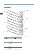
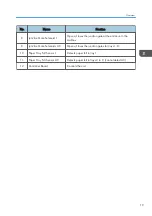
Page 16: ...3 Control board x2 x15 1 Replacement and Adjustment 14 ...

Page 17: ... to 128g m 14 lb 34 lb Bond Dimensions w x d x h 540 x 600 x 660 mm 21 3 x 23 6 x 26 in Weight Less than 15 kg 33 lb Power Consumption Less than 48 W Noise Less than 74 dB Stack Capacity 100 sheets each bin Power Source DC24V 5V from main machine Dimensions w x d x h 540 x 600 x 660 mm 21 3 x 23 6 x 26 in Weight Less than 15 kg 33 lb 15 ...

Page 18: ...Overview Layout No Part 1 Exit Roller 2 Transport Roller 3 Junction Gate 4 1 Bin Tray 5 5 Bin Tray 6 9 Bin Tray 2 Details 16 ...

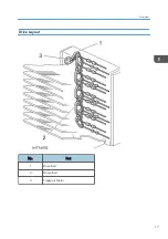
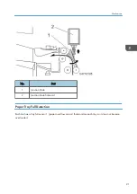
Page 19: ...Drive Layout No Part 1 Drive Belt 2 Driven Belt 3 Transport Motor Overview 17 ...

Page 20: ...sor 1 Detects misfeeds located between trays 1 and 2 4 Vertical Transport Sensor 2 Detects misfeeds located between trays 3 and 4 5 Vertical Transport Sensor 3 Detects misfeeds located between trays 5 and 6 6 Vertical Transport Sensor 4 Detects misfeeds located between trays 7 and 8 7 Vertical Transport Sensor 5 Detects misfeeds located at the exit to tray 9 2 Details 18 ...

Page 21: ...trance to the mailbox 9 Junction Gate Solenoids 2 9 Opens closes the junction gates for trays 1 8 10 Paper Tray Full Sensor 1 Detects paper full in tray 1 11 Paper Tray Full Sensor 2 9 Detects paper full in trays 2 to 9 cannot detect A5 12 Controller Board Controls the unit Overview 19 ...

Page 22: ... Transport Roller When the junction gate solenoid turns on the gate switches and the tray receives the paper When the uppermost tray is selected all solenoids stay off When the last paper s trailing edge passes the overflow sensor and the sensor turns off the paper has gone to the tray so the selected tray s junction gate solenoid and the main motor turn off Normally the speed of paper transport i...

Page 23: ...No Part 1 Junction Gate 2 Junction Gate Solenoid Paper Tray Full Detection Each bin has a tray full sensor 1 paper overflow sensor that monitors each tray so it does not become overloaded Mechanisms 21 ...

Page 24: ...s at the High level full detection will occur For example at the lowest PPM 12 sheets A3 when the sensor doesn t switch to Low by 40 sec after the detection the print job will be stopped The machine determines the following depending on the result of the detection and the machine state 2 Details 22 ...

Page 25: ...same tray while the paper overflow sensor remains ON In all states other than receiving paper with door closed no jam and no remaining paper The sensor stays on for more than 1 5 sec Not Full The sensor turns OFF Jam Detection Jam is detected with the five sensors in the picture below Mechanisms 23 ...

Page 26: ...No Part 1 Finisher Exit Roller 2 Entrance Junction Gate CS4010 3 Vertical Transport Sensor 4 Vertical Transport Sensor 2 5 Vertical Transport Sensor 3 6 Vertical Transport Sensor 4 2 Details 24 ...

Page 27: ... Transport Sensor 2 Late Jam No Change 352 Transport Sensor 2 Lag Jam No Change 353 Transport Sensor 3 Late Jam No Change 354 Transport Sensor 3 Lag Jam No Change 355 Transport Sensor 4 Late Jam No Change 356 Transport Sensor 4 Lag Jam No Change 357 Transport Sensor 5 Late Jam No Change 358 Transport Sensor 5 Lag Jam No Change 359 Main Machine Ordering Data Wrong Jam Cannot continue to receive pap...

Page 28: ...MEMO 26 ...

Page 29: ...MEMO 27 ...

Page 30: ...MEMO 28 EN ...

Reviews: