Jogging (Paper Alignment)
D372 26 SM
2.3 JOGGING (PAPER ALIGNMENT)
2.3.1 OVERVIEW
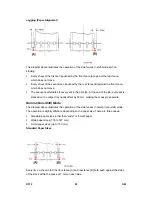
Two side fences, a rear fence and a front fence, move in and out to align the sides of the
paper stack. Each fence is controlled by an independent timing belt and motor.
The front fence motor [1] and timing belt [2] move the front fence [3] backward and forward.
The rear fence motor [4] and timing belt (not shown) move the rear fence [5] forward and
backward.
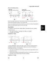
The diagram above shows the positions of the side fences.
1. When the copier exit sensor signals that that a sheet of paper has been sent from the
copier to the finisher, both fence motors switch on and move the side fences to the
start position.
The start position for each fence is set wider than the paper size selected for the job:
15 mm wider than the paper for shift mode.
7 mm wider than the paper for staple mode
10 mm wider than 12-in. paper for oblique stapling
12 mm wider than 12-in. paper for straight stapling
2. The paper is fed onto the output tray. The transport motor slows down the rotation of
Summary of Contents for D017
Page 1: ...D017 D018 D019 D020 D084 D085 SERVICE MANUAL 003320MIU...
Page 2: ......
Page 3: ...D017 D018 D019 D020 D084 D085 SERVICE MANUAL...
Page 4: ......
Page 5: ...D017 D018 D019 D020 D084 D085 SERVICE MANUAL 003320MIU...
Page 6: ......
Page 8: ......
Page 10: ......
Page 12: ......
Page 26: ......
Page 33: ...PRODUCT INFORMATION REVISION HISTORY Page Date Added Updated New None...
Page 34: ......
Page 46: ......
Page 51: ...Copier Installation D017 D018 D019 D020 D084 D085 2 5 SM Installation...
Page 175: ...PREVENTIVE MAINTENANCE REVISION HISTORY Page Date Added Updated New None...
Page 176: ......
Page 179: ...REPLACEMENT AND ADJUSTMENT REVISION HISTORY Page Date Added Updated New None...
Page 180: ......
Page 206: ...Photoconductor Unit PCU SM 4 26 D017 D018 D019 D020 D084 D085 6 Drum E White clip x1 F...
Page 262: ......
Page 264: ......
Page 293: ...TROUBLESHOOTING REVISION HISTORY Page Date Added Updated New None...
Page 294: ......
Page 299: ...Self Diagnostic Mode D017 D018 D019 D020 D084 D085 6 5 SM Trouble Shooting...
Page 303: ...Image Problems D017 D018 D019 D020 D084 D085 6 9 SM Trouble Shooting...
Page 309: ...Image Problems D017 D018 D019 D020 D084 D085 6 15 SM Trouble Shooting...
Page 323: ...ENERGY SAVING REVISION HISTORY Page Date Added Updated New None...
Page 324: ......
Page 333: ...D017 D018 D019 D020 D084 D085 SERVICE MANUAL APPENDICES...
Page 334: ......
Page 337: ......
Page 339: ......
Page 363: ......
Page 364: ...APPENDIX PM TABLES APPENDIX 2 PM TABLES REVISION HISTORY Page Date Added Updated New None...
Page 365: ......
Page 373: ......
Page 375: ......
Page 433: ......
Page 672: ......
Page 674: ......
Page 694: ......
Page 696: ......
Page 698: ......
Page 724: ......
Page 728: ......
Page 731: ...Covers SM 3 B793 Booklet Finisher B793 3 Remove the upper left cover C...
Page 745: ...Folder SM 17 B793 Booklet Finisher B793 6 Remove a connector 7 7 Remove 2 screws 8...
Page 746: ...Folder B793 18 SM 8 Remove the staple tray 9 9 Remove the guide 10 2 screws...
Page 790: ......
Page 792: ......
Page 794: ......
Page 816: ......
Page 818: ......
Page 822: ......
Page 826: ......
Page 1043: ...ARDF DF3030 D366 ARDF DF3030 REVISION HISTORY Page Date Added Updated New None...
Page 1044: ......
Page 1048: ......
Page 1074: ......
Page 1075: ...1 BIN TRAY BN3030 D367 1 BIN TRAY BN3030 REVISION HISTORY Page Date Added Updated New None...
Page 1076: ......
Page 1078: ......
Page 1084: ......
Page 1085: ...BRIDGE UNIT BU3020 D368 BRIDGE UNIT BU3030 REVISION HISTORY Page Date Added Updated New None...
Page 1086: ......
Page 1088: ......
Page 1097: ...DUPLEX UNIT AD3000 D369 DUPLEX UNIT AD3000 REVISION HISTORY Page Date Added Updated New None...
Page 1098: ......
Page 1100: ......
Page 1104: ......
Page 1112: ...Electrical Component D369 8 SM 4 Duplex transport motor B x 2...
Page 1121: ...BYPASS TRAY BY3000 D370 BYPASS TRAY D370 REVISION HISTORY Page Date Added Updated New None...
Page 1122: ......
Page 1124: ......
Page 1126: ......
Page 1128: ...Tray D370 2 SM 2 Remove the pins A x 1 each 3 By pass tray B x 1...
Page 1133: ...Feed SM 7 D370 Bypass Tray BY3000 D370 6 Separation pad D spring x 1...
Page 1138: ......
Page 1140: ......
Page 1142: ......
Page 1148: ......
Page 1150: ......
Page 1156: ......
Page 1176: ...Overview D372 20 SM No What Happens sure that the stapler is at its home position...
Page 1220: ......
Page 1222: ......
Page 1224: ......
Page 1254: ...Scanner Service Tables D383 6 SM Compression Notch Assignment...
Page 1260: ......
Page 1262: ......
Page 1264: ......


