background image


D124 

114 

Detailed Descriptions


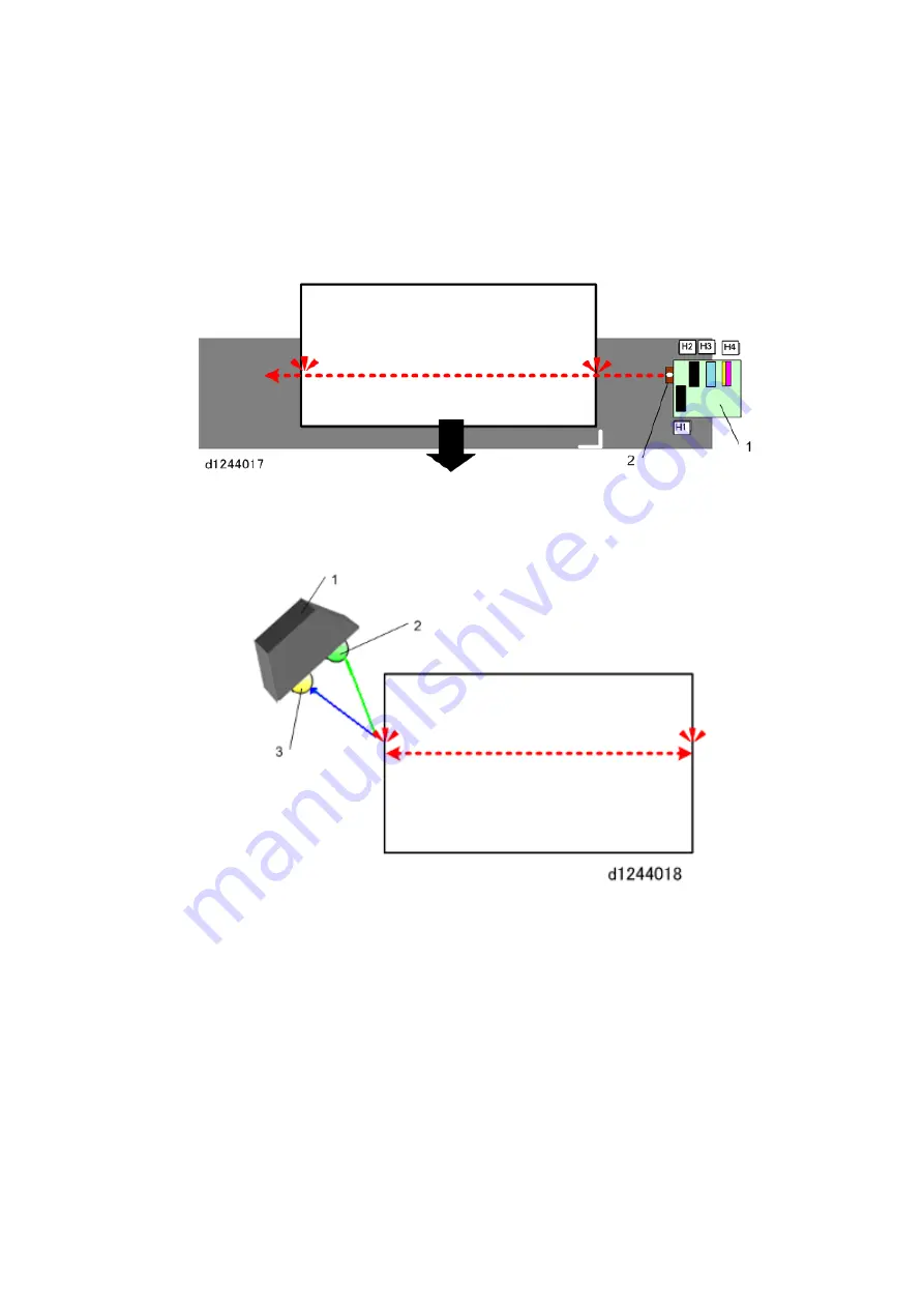
Dot position correction (color registration)

. The carriage moves across the 

paper during printing, so the ink drops cannot fall vertically. The readings of the 

DRESS sensor are used to adjust the timing of the piezo-electric elements in the 

print heads that release the ink. Timing is adjusted for the height of the carriage 

(and print heads), paper thickness, speed of the carriage, and print mode 

(uni-directional or b-directional). 


1.  When a job starts, the horizontal motor switches on and moves the carriage (1) 

across the paper so that the DRESS sensor (2) can detect the right and left edges 

of the paper. 


Summary of Contents for D124

Page 1: ...D124 DETAILED DESCRIPTIONS MANUAL ...

Page 2: ......

Page 3: ...Cover Switches 10 Ink Level Detection 11 Cutter 11 Paper Feed Control 12 Improved Productivity 13 1 2 GENERAL LAYOUT 14 1 3 MAIN UNIT LAYOUT 16 1 4 MOTORS CLUTCHES AIR RELEASE SOLENOID 18 1 5 SCHEMATIC DIAGRAM 21 1 6 ORIGINAL PATH PAPER PATH SENSORS 22 1 7 GENERAL OPERATION SEQUENCE 26 1 7 1 1 POWER ON 26 1 7 2 2 SCANNING 27 1 7 3 3 PAPER FEED 28 1 7 4 4 PRINTING 30 1 7 5 5 CUTTING 32 1 7 6 6 PAPE...

Page 4: ...2 2 5 1 CIS STRUCTURE 52 2 5 2 PRINTED IMAGE 53 2 6 LONG ORIGINAL OR SPECIAL ORIGINAL WITH CARRIER SHEET 54 3 IMAGE PROCESSING 55 3 1 IMAGE FLOW 55 3 1 1 COPY JOB IMAGE DATA FLOW 55 3 1 2 SCAN JOB IMAGE DATA FLOW 56 3 1 3 PRINT JOB IMAGE DATA FLOW 56 3 2 COPY MODE IMAGE PROCESSING 57 3 3 PRINT MODE IMAGE PROCESSING 59 3 4 COPY RESOLUTION COPY JOBS AND PRINT JOBS 60 3 4 1 COPY JOBS 60 3 4 2 PRINT J...

Page 5: ...5 5 1 OVERVIEW 95 5 2 INK CARTRIDGE 97 5 3 INK SUPPLY MECHANISM 99 5 4 CONTROLLING INK SUPPLY TO THE SUB TANKS 101 5 4 1 THE OCFS SYSTEM 101 5 4 2 CONTROLLING INK SUPPLY DURING PRINTING 103 5 4 3 AIR DETECTION AND AIR PURGING 103 5 4 4 AIR PURGE MECHANISM 104 5 4 5 AFTER AIR PURGING 105 6 PRINTING 106 6 1 PRINTING DRIVE MECHANISM 106 6 2 CARRIAGE UNIT 107 6 3 PRINT HEAD UNIT 110 6 4 PRINT HEAD 112...

Page 6: ...MENU ADJUSTMENTS 138 7 2 NOZZLE CHECK CLEAN AND FLUSH PRINT HEADS 140 7 2 1 NOZZLE CHECK 140 7 2 2 CLEAN PRINT HEADS 142 7 2 3 FLUSH PRINT HEADS 145 7 2 4 WHEN PRINTING CANNOT BE RESTORED 146 7 3 AUTO ADJUST HEAD POSITION 147 7 4 MANUAL ADJUST HEAD POSITION 150 7 5 ADJUST PAPER FEED 153 7 6 ADJUST PRINT POSITION 156 8 ELECTRICAL COMPONENTS 158 8 1 BOARD LAYOUT 158 8 1 1 SIB 158 8 1 2 OPERATION PAN...

Page 7: ...s a quick summary of the external components of the D124 More details are provided in later sections of this document 1 1 1 CONFIGURATION Six units comprise the machine No Unit Operation panel Scanner unit Main unit Roll Unit 1 standard Roll Unit 2 option Exit stacker ...

Page 8: ...D card USB card slots are placed on the right side of the operation panel Scan to media Media to Print SD card or USB clip memory One SD card slot and one USB memory slot is provided on the right side of the operation panel Warm up time Short warm up time less than 40 sec at 23 C 73 4 F Roll feed Two roll feed units one standard one option and manual bypass feed are possible A paper holding lever ...

Page 9: ... Yes Yes Controller GW GW Copying printing Ink Jet Technology Electrostatic photo HDD overwrite encryption Yes Std Yes Std Languages 20 Languages 18 Languages Media to print Yes Std No Memory Standard 3GB 250GB HDD 1GB 160GB HDD With Scanner Option 2GB 160GB HDD PDF batch print Yes Yes Printer function Standard Option Rear original output Yes Yes SDK Yes Yes With Printer Option Scan to media Yes S...

Page 10: ...e of the paper during printing Normally the machine prints on the right to left pass only but bi directional printing laying down ink on both passes left and right is also possible The operation of the horizontal motor is controlled by a long horizontal encoder strip 5 stretched across the width of the main unit A horizontal encoder sensor 6 mounted on the back of the carriage unit reads the codes...

Page 11: ...s the paper slightly stretched to prevent buckling The operation of the vertical motor is controlled by a vertical encoder wheel 5 mounted on the left side of the machine in front of the vertical feed motor A vertical encoder sensor 6 bracketing the edge of the vertical encoder wheel reads the codes on the edge of the wheel as it rotates to control vertical paper feed The vertical encoder HP senso...

Page 12: ...maintenance motor 1 raises the suction cap K1 unit head cap 2 that cleans the print heads raises the rubber scraper 3 moves the wipers 4 and drives the suction pump 5 The maintenance lift motor 6 raises the three print head caps K2 C YM unit heads caps 7 that protect the print heads from drying out and slides the cleaning unit 8 forward and backward The maintenance lift motor and the sliding clean...

Page 13: ...m 5 against the side of the flexible ink supply tube 6 The alternate pressure and release of the cam against the tube form enough suction to draw ink from the ink cartridge The ink is pumped through the tube and into the ink sub tank in the print head unit 7 which is mounted in the carriage unit 8 There are four short ink supply tubes one for each cartridge between the ink cartridge port and the i...

Page 14: ...the print heads by the maintenance unit during print head cleaning The ink collector tank has an ID chip that keeps a count and will signal when the tank is full and needs to be replaced A right ink sump 3 mounted behind the waste ink collector catches waste ink that is scraped from the surfaces of the heads during print head cleaning by the maintenance unit A left ink sump 4 on the left side of t...

Page 15: ... paper so the machine can position the image on the paper Skew correction Checks and corrects skew at the right edge of the paper If the edge is skewed more than 10 mm the machine rewinds the paper onto the roll Dot position correction color registration The carriage moves across the paper during printing so the ink drops cannot fall vertically The readings of the DRESS sensor are used to adjust t...

Page 16: ...in unit are mounted on separate stands Front Cover Switches The front cover 1 can be raised to remove paper jams and to load paper for bypass feeding The left front cover switch 2 and right front cover switch 3 are push switches that detect when the front cover is raised and lowered The guide pins on either end of the front cover are set in tracks which guide the ...

Page 17: ...t track The machine cannot operate until the front cover is down and all three of these switches are closed Ink Level Detection An OCFS On Carriage Fill Sensor system constantly monitors the ink level of each sub tank for each color Cutter A one direction cutter cuts roll paper from right to left and returns to the right side of the machine after cutting below the paper without interfering with pa...

Page 18: ...he rolls Encoder sensor 1 1 Counts rotations of the roll feed motor This pulse count is used to measure the operation time of the roll feed motor Encoder sensor 2 2 Counts the rotations of the edge roll core which vary depending on how much paper remains on the roll The number of rotations increases as the diameter of the paper roll decreases This pulse count is used in a calculation to determine ...

Page 19: ... used These black print heads are offset so they can cover a wider band with black ink This increases printing speed because a wider band can be covered with one pass in a black and white print During color printing B the K2 3 C 4 and YM 5 print heads are used The band is narrower because the forward sitting K1 print head is not used ...

Page 20: ...D124 14 Detailed Descriptions 1 2 GENERAL LAYOUT ...

Page 21: ...monitors ink level in the print head unit sub tanks during printing The air release solenoid 6 purges air from the ink supply system The maintenance unit 7 cleans the print heads mounted on the bottom of the carriage unit It contains two motors and three sensors that control the print head cleaning cycle This is described in a later section The ink supply unit 8 houses the ink cartridges and ink p...

Page 22: ... 2 Timing belt 3 Carriage unit 4 Horizontal encoder sensor 5 Horizontal encoder strip semi transparent 6 DRESS sensor 7 Cutter motor 8 Cutter 9 Cutter return switch 10 Cutter HP switch 11 Maintenance unit 12 Ink collector tank 13 Right ink sump 14 Left ink sump 15 Vertical motor ...

Page 23: ...itch 9 signals the cutter motor to reverse A lever and stopper in the cutter unit lowers the cutter into a lower race so that it passes from left to right below the paper When the cutter reaches the cutter home position on the right the cutter HP switch 10 switches the cutter motor off Print Head Cleaning The maintenance unit 11 cleans the print heads to prevent them from clogging with dry ink pap...

Page 24: ...D124 18 Detailed Descriptions 1 4 MOTORS CLUTCHES AIR RELEASE SOLENOID ...

Page 25: ...enance unit The maintenance lift motor raises the right print head caps K2 Y CM to cap and uncap the K2 C and YM print heads and moves the maintenance cleaning unit that holds the cleaning components suction cap wipers to the front and rear The maintenance motor raises and lowers the left print head cap suction cap to cap and uncap the K1 print head or to clean a print head The maintenance motor a...

Page 26: ... sub tanks The head lift motor 13 on the right side of the main unit frame controlled by two lift sensors housed in the carriage unit raises and lowers the carriage unit to adjust the gap between the paper and print heads for different thickness of paper This prevents the print heads from abrading the surface of thick paper during printing ...

Page 27: ... supply tubes 5 2 Air plungers 4 3 Air release solenoid 1 4 Main ink level sensor 2 FS2 1 5 Main ink level sensor 1 FS1 1 6 Ink supply pumps 5 7 Ink end sensors 5 8 Ink cartridges K C M Y 4 9 OCFS On Carriage Fill Sensors 5 10 On carriage feelers 5 11 Air sensors pairs 5 ...

Page 28: ...D124 22 Detailed Descriptions 1 6 ORIGINAL PATH PAPER PATH SENSORS ...

Page 29: ... 2 Original Path The original width sensors 1 detect the width of the original placed on the original table of the scanner unit The original set sensor 2 detects when the original is set on the original table It also functions as an original width sensor The original registration sensor 3 detects the leading edge of the original and stops the original feed roller The user can then manually make th...

Page 30: ...s a paper registration sensor during paper feed It detects the leading edge of the roll paper allows the paper to feed out of the machine for a prescribed distance and then signals the machine to reverse feed the paper to the registration standby position This sensor also functions as an image registration sensor and triggers printing when it detects the leading edge of the roll fed from the regis...

Page 31: ...passes the DRESS sensor 14 the sensor starts a pulse count and feeds edge of the paper as far as the registration standby position and stops The DRESS sensor knows how far to allow the paper to feed because the paper size was previously selected with the User Tools The carriage unit makes one pass over the paper so the DRESS sensor can detect the side edges of the paper and determine the width of ...

Page 32: ...ack to the maintenance unit 4 The positions of the print head OCFS feelers are checked to determine whether sufficient ink remains in each sub tank 5 The print head sub tanks are air purged and filled as needed and then the print heads are cleaned 6 The print heads are capped 7 The printer beeps twice when it is ready for operation Notes When the machine is powered on especially after a cold start...

Page 33: ...The original set sensor detects the presence of the original and the array of original width sensors detect its width 5 The scanner motor switches on and rotates the original entrance roller and original exit roller to feed the paper past the CIS unit which is below the original path 6 The original is fed to the upper exit If the original guide has been removed the original feeds straight out the ...

Page 34: ...ion RU 2 12 Cutter 6 Pre registration sensor 13 Exit roller 7 Bypass sensor 14 Exit sensor 1 Paper feed begins immediately from Roll Unit 1 if it was selected for the job or If Roll Unit 2 was selected for the job with paper from Roll Unit 1 at the registration standby position the machine reverse feeds the paper down to the paper standby position below the pre registration sensor and then feeds p...

Page 35: ...re paper and then the sensor checks the right edge again If the 1st and 2nd readings deviate by more than 10 mm this indicates excessive skew The paper is rewound and the operator must set the paper again 5 If no skew is detected the carriage moves to the left side of the machine and the DRESS sensor detects the left edge of the paper This detection of the right and then the left edge of the paper...

Page 36: ...rinting was selected only the first two print heads K1 and K2 both black are used If color printing was selected then the K2 C Y and M print heads are used If uni directional printing is selected then the print heads lay down ink only when the carriage unit passes from right to left If bi directional printing was selected the print heads lay down ink on both passes right to left and then left to r...

Page 37: ...Detailed Descriptions 31 D124 3 When an OCFS detects low ink the machine will refill the sub tank ...

Page 38: ...nted ends on the right side bi directional printing the carriage moves the right to its home position 2 Paper feeds a short distance and stops 3 The cutter motor switches on and drives the circular cutter from right to left to cut the paper 4 When the cutter reaches the left side of the machine the cutter drops into a track below the paper and then the cutter motor reverses and returns the cutter ...

Page 39: ...e feeds the paper out of the machine 2 When the exit sensor detects the trailing edge of the paper this signals job end 3 The paper transport fan switches off and the paper is reverse fed to the registration standby position 4 The machine is ready for the next job 5 If the machine remains idle for more than 14 min default it will enter the Sleep Mode ...

Page 40: ...red with a soft urethane coating This coating is soft and can be damaged quite easily even with a fingernail Never touch the surface of these rollers with bare hands Always hold the rollers by the bare ends where they are not coated Never use any type of strong organic solvent to clean the surface of these rollers Use only a cloth very slightly dampened with alcohol or water to clean the rollers ...

Page 41: ...ked screws across the top of the machine under the top cover These screws are positioned and adjusted at the factory Never loosen or attempt to adjust these screws Right Plate Screws You can see the heads of four paint locked screws around the top of the maintenance unit These screws hold a re enforcement plate Never loosen or remove any of these screws ...

Page 42: ...hich must always remain in the same position below the carriage print heads The two base plate screws at the back on the right rear panel should never be loosened or removed There are also two paint locked screws at the front One screw at the front below the switch bracket A on the right The other screw B is to the right of the temperature humidity sensor above the ink supply unit ...

Page 43: ...is also paint locked to remind you that it should not be removed Main Carriage Screws The illustration above shows the left cover of the carriage unit removed It is extremely important you never loosen or remove these screws Tampering with these screws could cause the carriage unit to fall out of alignment or onto the platen plates ...

Page 44: ...platen plate guide rod in place The platen plates should never be removed Sensor and Temperature Humidity Sensor Bracket This screw is paint locked However this bracket must be removed in order to remove the carriage unit The bracket must be reinstalled at exactly the same position so the sensors are positioned correctly ...

Page 45: ...YM 2400 001 Ink Collector Tank ID chip 1 Maintenance Unit 2102 001 1 An ID chip inside the ink collector tank records the count and disables the tank at the end of its service life The ID chip of the new tank automatically starts a new count No SP setting is required The left ink sump and right ink sump can also be easily replaced but these are not considered as PM Parts because their service life...

Page 46: ...SCANNER UNIT 2 1 SCANNER LAYOUT 2 1 1 SIDE VIEW No Item 1 Original width sensors 2 Original set sensor 3 Original entrance roller 4 Original registration sensor 5 CIS unit 6 Original exit sensor 7 Original exit roller 8 Scanner motor ...

Page 47: ...the scanner unit The original exit sensor 6 detects the leading and trailing edges of the original to check the feed timing of the original The original exit roller 7 feeds the original out of the scanner unit The scanner motor 8 drives the scanner entrance roller and the exit roller via a single timing belt Two safety micro switches not shown on the left side of the scanner unit disconnect power ...

Page 48: ...scriptions 2 1 2 FRONT VIEW No Item 1 Safety switches 2 Scanner motor 3 SIB 4 Original set sensor 5 Original registration sensor 6 Original exit sensor 7 CIS unit 5 elements 8 Original stop switch 9 Original width sensors ...

Page 49: ...inal when it is set on the original table Metric 10 sensors 9 original width sensors plus the original set sensor 1 which also functions as a width sensor Inch 11 sensors 10 original width sensors and the original set sensor 1 which also functions as a width sensor The NA machine has one additional width sensor 2 30 ...

Page 50: ...position 0 detect B series Metric or Architecture USA sizes The sensors to the right of center set sensor position 0 detect A series Metric or Engineering USA sizes If the original set sensor is the only one that detects paper the machine detects an A4 or 8 A size SEF original ...

Page 51: ...ed again for 1 sec This is called Delay 2 This gives the operator another chance to check that the original is straight If the original is not straight the user can push the original stop key on the right side of the scanner unit remove the original and try again The length of time for Delay 1 and Delay 2 to pause can be adjusted with User Tools System Settings General Features Original Feed Delay...

Page 52: ...l output trays when scanning thick originals The scanner motor 10 drives the entrance roller and exit roller in the scanner unit via a single timing belt 2 3 2 AUTO IMAGE DENSITY CORRECTION Auto Image Density Correction corrects the background density First the CIS unit 1 reads the surface of the white strips 2 on the platen plate There is one white strip mounted above each section of the CIS unit...

Page 53: ...ine To do this it starts 3 mm from the leading edge of the original B and reads 60 mm to the left and to the right of center These start positions can be adjusted with the following SP codes SP4901 005 Digital AE Start Position SP4901 006 Digital AE Left Start Position SP4901 007 Digital AE Right Start Position ...

Page 54: ...y adjusting the speed of the scanner motor with SP2116 Copier Sub Scan Magnification Correct Adjustment is done relative to the default setting 0 100 Reducing the setting increases the speed of the scanner motor and the image is reduced when it prints Increasing the setting reduces the speed of the scanner motor and the image is enlarged when it is printed ...

Page 55: ... scanner motor 1 a stepper motor and timing belt 2 drive the original entrance roller 3 and original exit roller 4 The original set sensor 5 turns the motor on when the original is set The original exit sensor 6 switches the motor off when the sensor detects the trailing edge of the original ...

Page 56: ...t 600 dpi During scanning to a file the speed of original feed is adjusted for resolution magnification is fixed at 100 The scanning speed increases as resolution or magnification lowers But to prevent color separation caused by excessive speed scanning speed does not increase any more when resolution or magnification reaches the following values and then image processing reduces the data Black an...

Page 57: ...o File Resolution 200 dpi Magnification 100 fixed Scanning speed 160 mm s with electronic magnification This graph shows the reciprocal relation between copy magnification and scan job resolution For example A copy reduced to 50 one half of an image at 100 600 dpi is reduced by removing half the pixels This is the same as a 300 dpi copy at 100 in other words the same as a document scanned to a fil...

Page 58: ...ite and color originals at a maximum of 926 5 mm 361 2 inches wide with 600 dpi A pair of safety switches 2 cut off the power circuits of the CIS unit when the scanner cover is raised This prevents the CIS unit from lighting up accidentally when the cover is open The CIS unit is made of 5 contact image sensors connected at 4 joints If you look from above the CIS sections are numbered from left to ...

Page 59: ...ailed Descriptions 53 D124 2 5 2 PRINTED IMAGE When you look at the copy to identify the areas scanned by each section the numbering is in the opposite sequence with CIS 5 on the left to CIS 1 on the right ...

Page 60: ...tely 50 ft The first starting point the reference point is upstream of the CIS The points can be entered with SP codes SP4993 SP4994 The speed of the scanner motor can be set in the range of 10 where it can be adjusted in fine increments 0 1 Look at the settings above Note that as more of the original feeds through the scanner unit the speed of the scanner motor is decreased slightly If the speed ...

Page 61: ...Detailed Descriptions 55 D124 3 IMAGE PROCESSING 3 1 IMAGE FLOW 3 1 1 COPY JOB IMAGE DATA FLOW ...

Page 62: ...D124 56 Detailed Descriptions 3 1 2 SCAN JOB IMAGE DATA FLOW 3 1 3 PRINT JOB IMAGE DATA FLOW ...

Page 63: ...py modes selected from the operation on the main machine are provided to achieve the best possible results in copying depending on the type and quality of the original Here is a brief summary of the copy modes as they appear in order of selection on the operation panel ...

Page 64: ...per Printed Photo Printed photos and artwork on magazine pages Copied Photo Photos or illustrations copied onto paper and printed in color Background Lines Forces background lines of section paper for example to dropout Forcing blue to drop out may be difficult Patched Original Text photos drawings pasted up on paper or boards for layout Generation Copy Originals copied many times in succession wi...

Page 65: ...s Normal Default Target for color reproduction quality in printing is RGB monitor color Color Black and White Aims for B W reproduction detected by the human eye CUD Print Adjusts colors so they are easily distinguished by those with color blindness POP Optimization Best quality of outstanding colors for POP printing Ink Save Best possible print production with less ink in order to conserve toner ...

Page 66: ...Translucent Color Standard Uni Dir No 600 x 600 15 Matte Film Monochrome Standard Uni Dir No 600 x 600 16 Matte Film Color Standard Uni Dir No 600 x 600 17 Coated CAD Monochrome High Speed Bi Dir Yes 600 x 300 18 Standard Bi Dir Yes 600 x 600 19 Coated CAD Color High Speed Bi Dir Yes 600 x 300 20 Standard Bi Dir Yes 600 x 600 21 Coated Monochrome Standard Uni Dir No 600 x 1200 22 Coated Color Stan...

Page 67: ...lucent Monochrome High Speed Bi Dir Yes 600 x 600 20 Standard Uni Dir No 600 x 1200 21 Quality Uni Dir No 600 x 600 22 Translucent Color High Speed Bi Dir No 600 x 600 23 Standard Uni Dir No 600 x 1200 24 Quality Uni Dir No 600 x 600 25 Matte Film Monochrome High Speed Uni Dir No 600 x 600 26 Standard Uni Dir No 600 x 1200 27 Quality Uni Dir No 1200 x 1200 28 Matte Film Color High Speed Bi Dir Yes...

Page 68: ...0 48 Quality Uni Dir No 600 x 600 In the table above Uni Dir means uni directional printing The print heads lay down ink in only one pass as the carriage unit moves from right to left Bi Dir means bi directional printing The print heads lay down ink in two passes as the carriage unit moves from right to left and then right to left Switching Yes No the operator can cannot switch between uni directi...

Page 69: ...e Checkers 1 Dot Line 8 Oblique Checkers 2 Dots Line 9 Checker Flag 10 Nozzle Check Pattern 11 All Solid IPU Test Patterns 4417 IPU Test Pattern Setting Pattern Selection No Pattern Name 0 Scanned Image 1 Gradation Main Scan A 2 Gradation Sub Scan B 3 Gradation RGBCMYK 4 Grid Pattern A 5 Slant Grid Pattern A 6 Scanned Grid Pattern A 7 Scanned Slant Grid A 8 Grid Pattern B 9 Scanned Grid Pattern B ...

Page 70: ...ensor 1 motor 3 Paper transport fan 13 Encoder sensor 2 paper 4 Registration roller 14 Roll rewind switch 5 Bypass sensor 15 Spool 6 Pre registration sensor 16 Paper exit guide 7 Feed roller 17 Paper exit guide switch 8 Roll feeder exit sensor 18 Exit sensor 9 Paper release sensor 19 Exit roller 10 Roll feeder entrance sensor 20 Cutter ...

Page 71: ... edge Next the vertical feed motor not shown on the left side of the machine turns on When the DRESS sensor 6 detects the leading edge the motors and roll feed clutch turn off and the machine checks for paper skew Then the roll feed motor and roll feed clutch turn 7 on and reverse feed This process opens the nip 1 between the roll feed roller and its idle roller The registration roller 8 now has t...

Page 72: ...paper feed motor rotates in reverse with the roll feed clutch 3 OFF the spool reverses for example to take up slack When the roll paper feed motor rotates in reverse with the roll feed clutch ON the feed roller rotates in reverse The cam 4 also rotates and this moves the idle roller 5 into and out of contact with the feed roller so the paper reverse feeds intermittently ...

Page 73: ...motor 3 stops A prompt appears on the screen and asks the user if the paper should be cut Cut or No Cut The operator presses Cut recommended The user then selects Paper Type and Thickness The roll paper feed motor 3 starts rotating clockwise This turns the shaft of the roll feed roller 2 and feeds the paper The roll paper feed motor rotates the roll feed roller via the drive gears 4 The paper cont...

Page 74: ...l feeder into the vertical feed path of the main machine When the leading edge of the paper reaches the pre registration sensor 3 the vertical motor on the left side of the machine turns on and rotates the registration roller 4 and exit roller 5 When the DRESS sensor 6 detects the leading edge of the paper the vertical motor stops ...

Page 75: ...lutch 2 also stop Then the clutch turns on again but the motor rotates counter clockwise When the motor turns in this direction the cam shaft 3 rotates and moves the idle roller 4 down until the paper release sensor 5 turns on The feed roller and idle roller are now separated ...

Page 76: ...turns on and drives the cutter across the paper to cut it The vertical feed motor turns on again feeds the paper forward out of the front of the machine a short distance 2 stops and then reverses When the DRESS sensor 3 detects the edge of the paper again it starts a count and then stops the paper at the registration standby position 4 above the registration roller 5 ...

Page 77: ...r Roll 1 reverse feed the paper from Roll Unit 1 When the pre registration sensor 2 detects the edge of the paper the machine reverse feeds the paper to the paper standby position 3 for Roll Unit 1 Then the motors turn off Initializing the First Paper described above is executed for the roll paper in Roll Unit 2 The leading edge of the Roll Unit 2 paper stops at the registration standby position a...

Page 78: ...tor 1 reverse feed the paper from the registration standby position 2 the roll feed clutch stays off so only the spool is reversing the paper and not the roll feed roller When the edge of the paper passes the pre registration sensor 3 the vertical motor stops When the edge of the paper reaches the roll entrance sensor 4 or after 5 seconds has passed whichever is first the roll feed motor also stop...

Page 79: ... feed roller When the edge of the paper reaches the roll entrance sensor 3 or after 5 seconds has passed whichever is first the roll feed motor stops Then the roll feed motor reverses briefly with the clutch on This closes the nip 4 between the roll feed roller and its idle roller So the next time paper is inserted the nip is already closed The operator then turns the roll by hand until the edge o...

Page 80: ...edge of the paper passes This signals roll end and the machine displays a message to alert the operator that the roll needs replacement If the trailing edge of the paper is attached to the roll core At the end of the roll the trailing edge of the paper remains attached to the roll core but the paper continues to feed The paper is pulled taut up against the actuator of the roll end sensor 3 This si...

Page 81: ...l encoder wheel 3 Vertical encoder sensor 4 Vertical encoder HP sensor 5 Timing belt 6 Registration roller 7 Exit roller The vertical motor 1 controlled by the vertical encoder wheel 2 vertical encoder sensor 3 and vertical encoder HP sensor 4 drives the timing belt 5 that rotates the registration roller 6 and the exit roller 7 ...

Page 82: ...CHANISM No Item 1 Paper holding lever cam 2 Pressure arm 3 Registration roller idle rollers 4 Vertical motor 5 Drive belt 6 Registration roller 7 Exit roller 8 Vertical encoder sensor 9 Vertical encoder wheel 10 Vertical encoder HP sensor 11 Exit sensor ...

Page 83: ...s done to load paper for bypass feed The vertical motor 4 uses one drive belt 5 to drive the registration roller 6 and the exit roller 7 The vertical encoder sensor 8 reads the codes notched on the edge of the vertical encoder wheel 9 as it rotates on the end of the shaft of the registration roller These readings are used to control vertical paper feed in the main machine The vertical encoder HP s...

Page 84: ...control machine operation Encoder sensor 1 3 Counts rotations of the roll feed motor This pulse count is used to measure the operation time of the roll feed motor Encoder sensor 2 4 Counts the rotations of the edge roll core which vary depending on how much paper remains on the roll The number of rotations increases as the diameter of the paper roll decreases This pulse count is used in a calculat...

Page 85: ...ge of the paper to the registration standby position This is done at the following times When the roll is replaced or swapped for another roll When the paper is fed back to the registration standby position after the paper is cut at the end of a job When the other paper roll is selected for paper feed For example if paper from Roll Unit 1 is at the paper registration position and Roll Unit 2 is se...

Page 86: ...ic is applied to both 2 in and 3 in to compensate for the differences in diameters with these rolls 100 mm 1 pulse count For a 2 in roll the maximum Normal paper 90 m φ112 mm the half count is at 3 above Vertical Feed Amount Table 100 mm 1 pulse count Remaining Pulse Count Roll Dia mm 100 Less than 98 φ173 90 99 to 107 φ161 80 108 to 116 φ149 70 117 to 127 φ137 60 128 to 141 φ125 50 142 to 158 φ11...

Page 87: ... pre registration sensor 1 detects the leading edge of the paper This turns the transport fan 2 The paper passes the registration standby position 3 above the registration roller When the DRESS sensor 4 detects the leading edge of the paper the operation of the fan is set to Duty 1 mode This pulls the paper down onto the perforated platen plates and keeps it perfectly flat for cutting and printing...

Page 88: ... edge of the paper and turns on the fan 2 The DRESS sensor 3 on the left side of the carriage goes ON when it detects the leading edge of the paper and switches operation of the fan to Duty 1 The paper transport fan remains in the Duty 1 phase while the paper feeds 79 mm past the registration standby position 4 This provides maximum suction to keep the leading edge of the paper flat When the leadi...

Page 89: ... is different for each paper size width and paper type As a general rule duty 1 is the highest setting to ensure that the leading edge of the paper remains flat as it passes over the platen The duty settings for thicker paper are much higher than those for thinner lightweight paper The duty settings are selected automatically as soon as paper size and type are selected for the job The duty levels ...

Page 90: ...20 30 30 30 620 to 841 30 30 30 841 or wider 30 30 30 Normal Duty Width mm Duty 1 Duty 2 Duty 3 279 4 to 420 50 30 30 420 to 620 50 30 30 620 to 841 50 30 30 841 or wider 50 30 30 4 5 4 TRANSLUCENT PAPER Thin Duty Width mm Duty 1 Duty 2 Duty 3 279 4 to 420 40 30 30 420 to 620 40 30 30 620 to 841 40 30 30 841 or wider 40 30 30 Normal Duty Width mm Duty 1 Duty 2 Duty 3 279 4 to 420 40 30 30 420 to 6...

Page 91: ...current operation level The optimum duty settings for each paper size and type are done at the factory before the machine is shipped SP1955 002 to 010 Adjusts fan duty in the range of 20 for the duty phases of different types of paper The firmware checks the current fan operation setting of the motor for the selected paper type and then uses a lookup table to fetch the specified setting the percen...

Page 92: ...em No Item 1 Paper entrance sensor 8 Registration roller 2 Paper feed roller 9 Registration standby position 3 Paper exit sensor 10 DRESS sensor 4 Paper standby position RU 1 11 Paper leading edge 5 Paper standby position RU 2 12 Cutter 6 Pre registration sensor 13 Exit roller 7 Bypass sensor 14 Exit sensor ...

Page 93: ...per 7 Roll feeder paper feed clutch ON and delay 50 ms 8 Paper feed Motor ON and feeds paper toward the pre registration sensor 9 Pre registration sensor ON 10 Vertical Motor ON and feeds paper The speed of the vertical motor is 3 mm s faster than the speed of the paper feed motor 80 mm s 3 mm s 11 Paper transport fan below the platen ON 12 The DRESS sensor on the left side of the carriage detects...

Page 94: ...eed motor and vertical motor switch ON again 20 When the DRESS sensor detects the leading edge of the paper it allows paper to feed 100 mm and switches the paper feed motor and vertical motors OFF 21 The horizontal motor switches ON and moves the carriage to the left side of the machine 22 The paper feed motor and vertical motor both switch on and feed the paper 60 mm 23 Now the paper feed motor r...

Page 95: ...t back to the right and stops 29 The DRESS sensor detects the left edge of the paper on the platen 30 The machine records the readings of the horizontal encoder for the right and left edges of the paper This is done to confirm the paper size with the selection done with an external coin operated device if one is attached ...

Page 96: ... If the operator selected paper cutting the cutter cuts the paper 33 Horizontal motor ON Carriage moves to left side of the machine and stops 34 Paper feed motor ON at 35 mm s and vertical motor ON at 100 mm s 35 Paper feeds 200 mm past cutter Paper feed motor OFF Vertical motor OFF 36 Cutter starts the cut 37 Cutter completes the cut when it reaches the left side of the machine 38 Cutter return s...

Page 97: ...racted so that the paper from the other roll can be fed for printing 1 The paper feed motor of the roll with paper at the registration standby position ON reverses at 120 mm s 2 The vertical motor ON reverses at 100 mm s The difference in the motor speeds keeps the paper taut 3 The pre registration sensor OFF and starts a pulse count 4 Once the paper has fed downstream back into the roll unit pape...

Page 98: ...1 switches on 2 The timing belt pulls the cutter 2 to the left as its circular blade 3 cuts the paper in its path 3 When the cutter reaches the cutter return switch 4 at the end of the cut the cutter motor reverses 4 Immediately the cutter drops into a lower race at 5 This lowers the cutter so it is below the paper 5 The motor and drive belt pull the cutter back to the right When the cutter reache...

Page 99: ...er onto the roll so there is no paper in the paper path 2 Next the operator presses the bypass feed icon on the Copier screen and then presses This opens a menu so the paper size and orientation can be selected 3 The operator raises the front cover and then raises the paper holding lever on the right side of the machine 4 The paper must be inserted with the right edge of the paper on the alignment...

Page 100: ...paper so the machine can calculate paper width and detect the leading edge of the paper The vertical motor switches on and reverse feeds the paper to the registration standby position and then switches off 7 A message on the operation panel asks the operator to confirm that the paper type is correct 8 After the operator confirms that the paper type is correct the print job starts 9 At the end of t...

Page 101: ... motors 5 7 Air release solenoid 1 8 Print head sub tanks 5 9 OCFS On Carriage Fill Sensors 5 10 Main ink level sensor 1 1 11 Main ink level sensor 2 1 1 There are four short ink supply tubes one for each cartridge between the ink cartridge port and the pumps The black tube splits into two supply tubes before the pumps one for K1 and one for K2 bringing the total of tubes to 5 ...

Page 102: ...et sturdy enough to prevent kinking and blocking the flow of ink The ink pump cam 5 driven by the ink pump motor 6 rotates against the ink supply tube to force ink through the tube The air release solenoid 7 provides pressure to push excess air out of the print head sub tanks The print head sub tanks 8 2 for black and 1 each for C Y M hold the ink supplied to the print heads from the ink pumps of ...

Page 103: ...he wrong position Each cartridge is provided with an ID chip 3 The machine monitors the ink levels based on counts of ink pump operation and stores this information in ID chips of the ink cartridges This count data is used to create the graphic display on the operation panel that shows the amount of ink consumed as well as the amount of ink remaining At the 5th level 35 to 20 When the ink level is...

Page 104: ...rtridge runs out of ink its end history is written onto the cartridge ID chip to permanently disable the cartridge and prevent it from being re used When an ink cartridge is inserted the ID chip 1 contacts a CCB 2 at the back of the ink supply unit slot When the ID chip and CCB Cartridge Control Board make contact this tells the machine that the cartridge is inserted correctly Ink usage is based o...

Page 105: ...into the ink supply port Ink flow flows through the cylinder 3 and over the plunger 4 as the ink pump motor 5 pumps ink from the cartridge While ink is flowing smoothly the actuator 6 on the end of the plunger remains outside the gap of the ink end sensor 7 When the ink in a cartridge runs out the ink pump motor continues to try to draw ink from the ink port But with no ink this creates a negative...

Page 106: ...s a side view of the ink pump mechanism The ink pump motor 1 drives the ink pump cam 2 counter clockwise and compresses the ink supply tube 3 The pressure on the tube 4 drives the ink bolus 5 ahead of the cam and creates enough suction to pull ink through the tube behind the pressure point This action of the cam alternately applying and releasing pressure against the side of the tube drives the in...

Page 107: ...ures that the ink level in each tank is constantly monitored Printing does not have to be interrupted to move the carriage to the right to check the ink levels as in previous ink jet models The OCFS system contains the following parts An actuator arm 1 is attached to a hinge 2 at the rear The center of the actuator is mounted on a weak spring 3 attached to the flexible side of the ink sub tank Whe...

Page 108: ... takes longer for it to move from right to left through and then out of the gap of the OCFS The sides of the sub tanks are flexible The sides may bend out slightly when the tank is full 1 and then gradually collapse as ink is drained from the tank 2 and 3 The actual level of the ink does not change at 2 and 3 even though there is less ink in the tank However if air enters the tank 4 the air sensor...

Page 109: ... machine s software to be enough to turn the sensor back on After that the machine continues to pump ink a very short time tsec This is the ink full position 6 5 4 3 AIR DETECTION AND AIR PURGING The air sensors on top of each ink sub tank check for the presence of air in the tanks Air is purged from the tank after it is detected and then the sub tank is refilled with ink The air purge filling and...

Page 110: ... unit When the carriage unit has positioned the print head tank 1 behind the air release solenoid 2 the solenoid switches on and pushes the plunger 3 The plunger pushes in the purge valve 4 and the excess air is purged from the sub tank After the air has been purged the ink supply motor turns on to supply more ink to replace the purged air with ink As more ink flows into the tank the actuator move...

Page 111: ...tor of K1 only Two main ink level sensors are required because the K1 print head is not level with the other 4 print heads 3 The machine records how far the carriage has moved along the horizontal encoder and stores this as the new Tank Full Position 4 At the end of a job the machine moves the carriage to the main ink level sensor to compare with the most recent Tank Full Position This sequence is...

Page 112: ...when the motor alternately rotates forward reverse The horizontal encoder sensor 4 brackets the top edge of the horizontal encoder strip 5 which stretches behind the drive belt and across the platen The sensor reads the timing notches from the strip as the carriage is driven left and right by the horizontal motor This controls the operation of the motor and movement of the carriage unit during pri...

Page 113: ...d K1 4 Guide rod 16 Print head K2 5 HRB Head Relay Board 17 Print head C 6 COM 18 Print head YM 7 Horizontal encoder sensor 19 DRESS sensor 8 Horizontal encoder strip 20 Ink level sensor 1 9 Print head thermistors 21 Ink level sensor 2 10 HT1 Head Tank K1 22 Temperature humidity sensor 11 HT2 Head Tank K2 23 Head lift motor 12 HT3 Head Tank C 24 Head lift sensors ...

Page 114: ...tric elements above the nozzles that release ink during printing There is one piezoelectric element for each print head K1 10 K2 11 C 12 and YM 13 An electric charge applied to the element makes it expand and discharge ink through the print head nozzles and onto the paper below At the beginning of a print job the carriage moves left then back to the right so that the DRESS sensor 14 on the side of...

Page 115: ...ontrol the raising and lowering of the carriage with the head lift motor The K1 print head H1 sits forward of the K2 print head H2 in the direction of paper feed This allows a greater band of coverage during black and white printing Three nozzles at the rear section of K1 and three nozzles at the front section of K2 overlap the same area on the paper However the arrangement of the nozzle ports is ...

Page 116: ...RINT HEAD UNIT No Item Qty 1 Head thermistor Black 1 2 Head thermistor Color 1 3 Air sensors pairs 5 4 Purge valves 5 5 Ink sub tanks K1 K2 C Y M 5 6 Ink sub tank feelers 5 7 Filter units 5 8 Print head units K1 K2 C YM 4 9 Print heads 5 ...

Page 117: ...olenoid not shown The ink sub tanks 5 hold the ink pumped from the ink cartridges by the ink supply unit One ink sub tank feeler 6 is attached to the side of each ink sub tank The OCFS On Carriage Fill Sensors and the stationary main ink level sensors on the right side of the machine check the positions of these feelers to determine the level of ink in the sub tanks The feeler arms are attached to...

Page 118: ...te Each print head 1 is comprised of the above parts When a small electric charge is applied to the piezoelectric element 1 this causes it to expand and expel ink under pressure The vibration plate 3 and flow plate 4 apply the ink evenly to the back of the nozzle array plate 5 The ink flows evenly through the ports of the nozzle array plate ...

Page 119: ...the change in reflectivity between the paper and platen at the edges The DRESS sensor performs these functions Paper width detection The sensor checks the right and left edges of the paper on the platen to check the size of the paper Image registration Detects the leading edge right edge and left edge of the paper so the machine can position the image on the paper Skew correction Checks and correc...

Page 120: ... adjust the timing of the piezo electric elements in the print heads that release the ink Timing is adjusted for the height of the carriage and print heads paper thickness speed of the carriage and print mode uni directional or b directional 1 When a job starts the horizontal motor switches on and moves the carriage 1 across the paper so that the DRESS sensor 2 can detect the right and left edges ...

Page 121: ...signed for different types of paper to compensate for any difference in the reflectivity of their surfaces The readings of the DRESS sensor for the left and right margins are used to determine the horizontal placement of the image on paper This can be adjusted with SP1002 Print Position Adjustment This adjustment determines where the moving carriage starts and ends printing with every horizontal p...

Page 122: ...perature near the print heads is critical because the temperature can affect the viscosity of the ink at the ink nozzles At low temperatures the viscosity of the ink becomes high and can slow ink flow At high temperatures the viscosity of the ink becomes low and can cause ink to spill and run The adjustment is done by changing the duty strength of electrical charge used to activate the piezoelectr...

Page 123: ...uctuation in temperature The readings of the K2 print head thermistor and the temperature humidity sensor are used together to calculate the operating temperature of the machine If the machine overheats and the operating temperature exceeds the maximum temperature the machine will shut down automatically and will not restart until it has cooled and been cycled off on The machine must be cycled off...

Page 124: ...abrading the paper during printing 6 7 1 HEIGHT ADJUSTMENT MECHANISM No Item 1 Head lift motor 2 Cam 3 Carriage unit 4 Head lift sensor 1 5 Head lift sensor 2 When the operator selects the setting to change the height of the carriage the carriage moves to the right so that the coupling on the end of the shaft can engage the head lift motor 1 The head lift motor rotates the cam 2 and raises the car...

Page 125: ... head lift motor 6 7 2 RAISING AND LOWERING THE PRINT HEADS The carriage unit and print heads can be raised to two high positions 1 mm 2 mm to eliminate smearing caused by the print heads rubbing across the surface of thick paper The Prevent Paper Abrasion setting must be done with the User Tools menu before starting the print job 1 Press the on the machine operation panel 2 Touch System Settings ...

Page 126: ...nit to the right side of the machine where the coupling of the lift motor engages the lift shaft The lift cam 1 and actuator 2 are attached to this shaft When the lift motor rotates the shaft the actuator passes through the gaps of head lift sensor 2 3 and head lift sensor 1 4 When the actuator reaches the position for the selection A B or C the shaft locks in place and then the carriage moves awa...

Page 127: ...ong 2 mm position these settings remain in effect until the operator repeats the selection procedure The print heads can be capped with the carriage raised to the Weak and Strong positions However bi directional printing is not allowed with the print heads raised The setting must be switched OFF standard to use bi directional printing ...

Page 128: ...idle Lowers the print heads at the start of a job to uncap the print heads Cleans the print heads when required No Item 1 Carriage unit 2 Maintenance unit 3 Print head cap K1 Suction cap 4 Slide sensor 5 Maintenance motor 6 Suction pump 7 Suction cap sensor 8 Suction cap actuator 9 Color print head caps K2 C YM 10 Lift lever K2 C YM 11 Carriage stopper 12 Lift sensor 13 Lift sensor actuator 14 Lif...

Page 129: ...ion cap 2 to prevent it from drying out At the start of the next job the maintenance motor 3 rotates forward and lowers the suction cap to uncap the K1 print head At the end of the job the carriage unit moves to the right and positions itself over the maintenance unit The maintenance motor rotates forward again and raises the suction cap to cap the K1 print head The rotating suction cap actuator 4...

Page 130: ... sealed by the print head caps 2 At the start of the next print job the lift motor 3 rotates forward and lowers the K2 C and YM caps to uncap the K2 C YM print heads The rotating lift actuator 4 mounted on a shaft with a cam driven by the lift motor and lift sensor 5 control the lowering of the three print caps The caps rest on the absorbent cap pads 6 while they are down ...

Page 131: ...s the carriage unit so that the caps and print heads are aligned The maintenance lift motor 2 rotating forward raises the K2 C Y M print head caps not shown on the lift lever 3 and covers the print heads to prevent them from drying out The rotating lift actuator 4 mounted on a shaft with a lift cam driven by the lift motor and lift sensor 5 control the raising of the caps ...

Page 132: ...n the K2 C and YM print heads This step is done for cleaning the K2 C and YM print heads in order to position the suction cap print head cap for K1 correctly If only the K1 print head is to be cleaned the cleaning unit is positioned to start cleaning immediately with the suction cap forward at A At the start of the cleaning cycle the carriage unit 1 positions itself over the maintenance unit 2 The...

Page 133: ... activates the slide sensor 9 the lift motor switches off with the cleaning unit at the rear Step 2 Raising the Suction Cap The carriage moves to the left and stops with the print head 1 to be cleaned directly above the suction cap 2 The maintenance motor 3 rotates forward and raises the suction cap The suction cap actuator 4 attached to the shaft with the cam driven by the maintenance motor to ra...

Page 134: ...ases the suction tube 3 to create enough pressure to draw ink from the surface of the print head 4 The ink is drawn through the tube which exits at the back of the maintenance unit 5 and continues down to the ink collector tank below the maintenance unit on the right side of the machine The suction cap lowers away from the print head after suctioning ink for the prescribed time ...

Page 135: ...er 1 is raised to the surface of the print head The knock lever 2 taps the edge of the scraper to scrape ink from the print head The ink falls into a vent 3 which opens over the right ink sump below the maintenance unit Next the linkage cocks the spring loaded wipers 4 to the rear and then releases them so that they spring forward and flick any remaining ink into the vent This is done twice This c...

Page 136: ... can affect the quality of printing To prevent the drying or thickening of ink around the nozzles the machine will execute a maintenance cleaning cycle appropriate for the length of time that the print heads have remained idle This is done automatically without intervention by the operator The machine monitors two phases of downtime Idle time 1 Starts after the last sheet exits and all the print h...

Page 137: ...me cleaning Ink fill sequence Downtime cleaning 1 The cycle is executed for the affected print head unit only The maintenance cycle could be brief or require several minutes to complete depending on ambient conditions and how long the print heads have remained idle Approximate Times Required for Cleaning No Downtime Approximate Time 1 10 h 16 sec 2 10 and 24 h 9 sec 1 3 24 h and 3 days 3 min 4 3 d...

Page 138: ...le condition is corrected with periodic automatic cleanings while the printer is in use greatly extending the length of time the machine can be used without operator intervention Mist count A mist count triggers automatic cleaning This mist count can be extended to increase the timing between automatic cleanings The mist count which determines the intervals between automatic cleanings has been dou...

Page 139: ...ignal an error if the tank is not installed or not set correctly Printing cannot be done unless the tank is set correctly This sensor also detects when the ink collector tank is full The right sump 4 resides behind the ink collector tank and directly below the maintenance cleaning unit This is an open sump that collects the ink that is wiped and scraped from the print heads at the end of the clean...

Page 140: ...tly Prompts alert the operator when the tank is near full and then full These alerts are triggered by the information stored in the ID chip of the tank A software count totals the usage of the tank in the number of times the maintenance unit sucks ink from the print heads during the head maintenance cycle The count is stored in the ID chip of the ink collector tank The near full alert is triggered...

Page 141: ...ine and the machine will continue to operate Tank full A prompt appears on the operation panel of the machine If a page is being printed the job will finish and then the machine will shut down and cannot be used until after the tank has been replaced Adjusting SP2507 001 and 002 is not recommended ...

Page 142: ...ink from the cleaning plate and drops the ink down into the sump below The wiper operation count is stored in NVRAM The right ink sump has no ID chip The tank is near full at 125 cc and full at 147 cc The estimated time between replacements is about 5 years Prompts Tank near full A prompt appears on the operation panel of the machine and the machine will continue to operate Tank full A prompt appe...

Page 143: ... machine will shut down and cannot be used until after the tank has been replaced The count must be reset with SP2505 001 after the left ink sump has been replaced There is no sensor to detect when the left ink sump is removed and inserted The machine refers to a lookup table to determine how to execute purging The purge intervals and amount of ink released is determined by the ambient temperature...

Page 144: ...G AND ADJUSTMENT 7 1 MAINTENANCE MENU ADJUSTMENTS There are seven important adjustments on the Maintenance Menu that the service technician must be familiar with 1 Press the button on the operation panel 2 Touch Maintenance to open the Maintenance Menu ...

Page 145: ...tion Do this procedure if you see broken vertical lines or blurred smeared or streaked colors Manual Adjust Head Position Do this procedure if the Auto Adjust Print Head Position execution fails Print Nozzle Check Pattern Print a Nozzle Check Pattern to detect blockages in the flow of ink from one or more of the print heads Clean the print heads up to three times If the third cleaning fails flush ...

Page 146: ...ern Selection Feed Station Paper Bypass Location Bypass feed Paper Input Location 1 Roll Unit 1 Paper Input Location 2 Roll Unit 2 Option The first selection will not display if paper is not set for bypass feed The third selection will not display if Roll Unit 2 is not installed 4 Select the paper feed station and then touch OK A message will ask you to wait while the pattern is printing 5 When th...

Page 147: ... Menu Check the Nozzle Check Pattern Normal If the print heads are operating normally none of the lines are broken Abnormal If you see bare patches caused by broken lines one or more print head need cleaning or flushing 7 Go to the next section below to clean the print heads ...

Page 148: ...or white patches in the in a printed Nozzle Check Pattern 1 First always check the ink level indicator in the printer driver to confirm that there is ink in the cartridge If one or more ink tanks are empty replace the ink cartridge and then print another Nozzle Check Pattern 2 Touch Clean Print heads There is one selection for each print head unit ...

Page 149: ...e print heads require cleaning 3 Touch each selection once to select the print head for cleaning and then touch Start A message will ask you to wait while the print heads are being cleaned Cleaning one print head takes about 60 sec The Magenta and Yellow print heads require about 120 sec 4 When the message tells you that print head cleaning has completed touch Exit ...

Page 150: ...tern and check the results 9 If one or more pattern is abnormal repeat the cleaning procedure from Step 3 Be sure to select only the print head where the pattern is broken 10 After the third cleaning if one or more of the patterns is abnormal go to the next section below and flush the print head where the pattern is abnormal Print head flushing consumes a significant amount of ink Never flush the ...

Page 151: ...t least three times 1 Touch Flush Print heads 2 Select the print head where the pattern is broken and then touch Start A message asks you to wait while the print head is flushing Flushing a print head requires about 3 minutes 3 When the message tells you that the flushing is completed touch Exit 4 The display will loop back to the Maintenance Menu Touch Print Nozzle Check ...

Page 152: ...ern is abnormal let the machine remain idle for 10 minutes 4 Execute two more cleanings and one flushing Be sure to print a Nozzle Check Pattern after each cleaning and the flushing When you have produced an unbroken Nozzle Check Pattern you can stop 5 After the flushing if the Nozzle Check Pattern is still not perfect let the machine remain idle for 8 hours 6 Execute three more cleanings and one ...

Page 153: ...ADJUST HEAD POSITION Adjust the print head position if you see these problems in the prints Broken vertical lines Blurred or streaked colors 1 Press the button on the operation panel 2 Touch Maintenance 3 Touch Auto Adjust Print Head Position ...

Page 154: ...Roll Unit 2 Resolution Speed Draft Standard Standard quality Quality High quality 4 Select the Target Location and Resolution and then touch Start Printing A message will ask you to wait while the adjustment is done and a pattern prints If the adjustment succeeded the pattern will look like the one above The black arrow indicates the direction of paper feed ...

Page 155: ...Detailed Descriptions 149 D124 If the automatic adjustment fails a message will say Failed to adjust and tell you to do the adjustment manually See the next section below ...

Page 156: ...previous section fails 1 Press the button on the operation panel 2 Touch Maintenance 3 Touch Manual Adjust Head Position Target Location Paper Source Paper Bypass Location Bypass paper feed Paper Input Location 1 Roll Unit 1 Paper Input Location 2 Roll Unit 2 Resolution Speed Draft Standard Standard quality Quality High quality ...

Page 157: ...and Resolution and then touch Start Printing A message will ask you to wait while the test pattern prints 5 Look at the test pattern Identify the number of the column where the square is faintest Write down these values for reference A4 B2 etc 6 Touch Adjustment ...

Page 158: ...ions 7 Enter the values for each row Just press the plus or minus button the numbers will appear automatically 8 Print another test pattern to make sure that the numbers you entered correspond to the results in the test pattern ...

Page 159: ...al lines Patchy images uneven filled areas White lines at regular intervals 1 Press the button on the operation panel 2 Touch Maintenance 3 Touch Adjust Paper Feed 4 Select Print Test Pattern for the paper feed source Paper Bypass Location Bypass paper feed Paper Input Location 1 Roll Unit 1 Paper Input Location 2 Roll Unit 2 ...

Page 160: ...D124 154 Detailed Descriptions 5 Touch Start Printing 6 The adjustment value appears to the left of the lightest gray square with straight horizontal lines on both sides 7 Touch Adjustment ...

Page 161: ...tailed Descriptions 155 D124 8 Touch the plus or minus key to enter the number where you identified the correct value in the test print Pressing either key increments decrements the numbers automatically ...

Page 162: ...here printing starts 1 Press the button on the operation panel 2 Touch Maintenance 3 Touch Adjust Print Position 4 Select Print Test Sheet for the paper feed source Paper Bypass Location Bypass paper feed Paper Input Location 1 Roll Unit 1 Paper Input Location 2 Roll Unit 2 5 Touch Start Printing A message will ask you to wait while the test sheet is printing ...

Page 163: ...eet 180 degrees A is the top margin and B is the left margin 8 Touch the arrow keys to adjust the margins Increasing the value for the top and left margins moves the print position down and to the right You will see the blue square move as you change the settings so you can confirm the effect of the changes ...

Page 164: ...ards For more details please refer to the point to point diagram 8 1 1 SIB SIB Scanner Interface Board Located at the left rear corner of the scanner unit interfaces with the five CIS elements and corrects sub scanning Image data scanned by the CIS elements is converted from analog to digital data by the SIB and then sent to the IPU for processing ...

Page 165: ... is the board that controls the USB connection points on the right side of the operation panel LCDC LCD Controller Controls the operation panel OP L Operation Panel Left Relays key presses from keys located on the left side of the panel Also contains the LEDs for the left side keys OP R Operation Panel Right Relays key presses from keys located on the right side of the panel Also contains the LEDs...

Page 166: ...laced with a larger mother board if the file format converter is installed IPU Image Processing Unit The IPU controls image processing It is only partially visible with the rear cover removed because it is mounted behind the MCU MCU Main Control Unit This is the engine control board The MCU manages Base engine control scanning control image processing control image writing control Basic I O functi...

Page 167: ...nt to DC current for the machine 8 1 4 OPTION BOARDS REAR 1 Wireless LAN Enables wireless communication 2 File Format Converter Also called MLB Media Link Board 3 Roll Feed Unit 2 2nd Roll Unit Option 4 Copy Data Security Prohibits copying of currency and other restricted items ...

Page 168: ...hine It does the following System control Base engine control Scanner control Image processing The MCU also sends load signals and supplies power to Base engine high voltage power pack motors sensors solenoid and clutch Scanner sensors motors etc The MCU DIP switches must always be OFF default and they must not be changed in the field ...

Page 169: ...s 163 D124 IPU Image Processing Unit The IPU Image Processing Unit processes image data from the CIS Contact Image Sensors 8 1 6 PSU The PSU Power Supply Unit supplies DC power for all electrical components in the machine ...

Page 170: ...RD The controller board controls the memory and all peripheral devices The GW architecture controls all applications i e copying printing and scanning The controller board has board slots and SD card slots that allow installation of the controller options ...

Page 171: ...eads this strip when the carriage moves from side to side and uses these readings to control operation of the motor M05 Roll Feed Motor RU1 Drives the roll paper feed roller that feeds the roll paper from Roll Unit 1 M06 Roll Feed Motor RU2 Drives the roll paper feed roller that feeds the roll paper from Roll Unit 2 M07 Maintenance Lift Motor Raises and lowers the color cradle K2 C YM caps during ...

Page 172: ...4 Head Relay Board Mounted behind the print heads in the carriage This board 1 Relays the readings of the DRESS sensor mounted on the left edge of the carriage unit 2 Receives and relays signals from the ink collection tank to the control board PCB05 COM PCB5 Located in the carriage unit behind the K1 print head relays signals between K1 print head unit and the HRB PCB06 MB PCB6 Mother Board Inter...

Page 173: ...on the left side of the machine is centered in the gap of this sensor The sensor reads the code on the rim of the vertical encoder wheel as it rotates to control the operation of the vertical motor during paper feed S03 Vertical Encoder HP Sensor Mounted opposite and lower than the vertical encoder sensor on the left side of the machine this sensor also reads the code on the rim of the vertical en...

Page 174: ...eration of the maintenance motor when it slides the K1 cradle to the front home position or to the rear during the print head cleaning cycle S22 Maintenance Lift Sensor Controls the operation of the maintenance lift motor that raises and lowers the color cradle K2 C YM during capping S23 Main Ink Level Sensor 2 Checks the position of the K2 C Y or M OCFS actuator after purging air from the tank Af...

Page 175: ...it It performs both paper registration and image registration S48 Horizontal Encoder Sensor Detects the long encoder strip mounted behind the horizontal drive belt Controls the operation of the horizontal motor which drives the carriage unit during printing S49 Head Lift Sensor 2 The head lift motor a stepper motor rotates an actuator in and out of the gaps of head lift sensor 1 and 2 to adjust th...

Page 176: ...after cutting Reverses the cutter motor which moves the cutter back to the home position on the right side of the machine SW06 Paper Exit Guide Switch Detects when the exit guide plate on the front of the machine is opened and closed SW07 Roll Rewind Switch RU1 Located on the inside cover of the right end of Roll Unit 1 Two presses rewinds the paper onto the paper roll SW08 Roll Rewind Switch RU2 ...

Page 177: ...om switching on while the cover is open TH1 Head Thermistor K1 Monitors the temperature of the black print head unit K1 TH2 Head Thermistor K2 C2 Monitors the temperature of the color print head units K2 C YM No Component Function Other Other LCD Liquid Crystal Display This is the display of the machine operation panel Other Touch Panel The touch sensitive panel covering the LCD of the machine ope...

Reviews: