Detailed Descriptions
127
D124
The gears rotate a shaft with a large cam (5) between two swinging plates
attached to the slide arm (6) linked to the cleaning unit (7)
When the cam pushes the front plate forward, the slide arm and cleaning unit
move to the rear.
When the slide actuator (8) (attached to the same shaft driven by the lift motor)
activates the slide sensor (9), the lift motor switches off with the cleaning unit at
the rear.
Step 2: Raising the Suction Cap
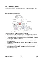
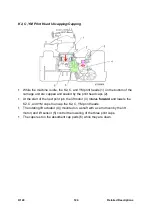
The carriage moves to the left and stops, with the print head (1) to be cleaned
directly above the suction cap (2).
The maintenance motor (3) rotates forward and raises the suction cap.
The suction cap actuator (4) (attached to the shaft with the cam driven by the
maintenance motor to raise the suction cap) and suction cap sensor (5) signal the
machine to turn off the motor when the cap is up and sealed on the print head.
Summary of Contents for D124
Page 1: ...D124 DETAILED DESCRIPTIONS MANUAL ...
Page 2: ......
Page 20: ...D124 14 Detailed Descriptions 1 2 GENERAL LAYOUT ...
Page 24: ...D124 18 Detailed Descriptions 1 4 MOTORS CLUTCHES AIR RELEASE SOLENOID ...
Page 28: ...D124 22 Detailed Descriptions 1 6 ORIGINAL PATH PAPER PATH SENSORS ...
Page 62: ...D124 56 Detailed Descriptions 3 1 2 SCAN JOB IMAGE DATA FLOW 3 1 3 PRINT JOB IMAGE DATA FLOW ...


