Detailed Descriptions
165
D124
8.2 DESCRIPTION OF ELECTRICAL COMPONENTS
No.
Component
Function
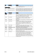
Counter
CO1
Main Counter
The mechanical counter that counts machine throughput.
HDD
HDD1
HDD
160 GB Hard Disk Drive
Motors
M01
Paper Transport Fan
The large fan mounted below the perforated platen plates. This
fan creates the suction that holds the paper on the paper path.
M02
Cutter Motor
Drives the cutter to the left and right across the paper path when
cutting paper. The cutter cuts as it moves from right to left.
When the cutter reaches the left side, the cutter return sensor
reverses the motor. A guide lever falls into a lower track that
lowers the cutter so that it passes under the paper on its return
to the home position on the right.
M03
Vertical Motor
The vertical motor drives the paper feed rollers and exit rollers
in the main machine. The operation of this motor is controlled by
the vertical encoder sensor and vertical HP sensor which read
the encoded rim of the vertical encoder wheel.
M04
Horizontal Motor
Mounted at the left rear corner of the printer, the horizontal
motor alternately runs forward and reverse to drive the timing
belt that moves the carriage to the left and right during printing.
The operation of the motor is controlled by the horizontal
encoder strip, which is stretched across the width of the printer
and threaded through the horizontal encoder sensor on the right
rear corner of the carriage unit. The sensor reads this strip when
the carriage moves from side to side and uses these readings to
control operation of the motor.
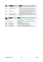
M05
Roll Feed Motor: RU1
Drives the roll paper feed roller that feeds the roll paper from
Roll Unit 1.
M06
Roll Feed Motor: RU2
Drives the roll paper feed roller that feeds the roll paper from
Roll Unit 2.
M07
Maintenance Lift Motor
Raises and lowers the color cradle (K2, C, YM caps) during
capping and the print head cleaning cycle. The maintenance lift
sensor controls operation of this motor during raising and
lowering.
M08
Maintenance Motor
The maintenance motor: 1) Raises and lowers the print head
suction cap, 2) Drives the pump that sucks waste ink from the
print heads through the suction cap, and 3) Drives the wiper
blade and wiper in the cleaning unit.
M09
Head Lift Motor
Raises and lowers the carriage to adjust the gap between the
print heads and the paper for different thicknesses of paper. The
motor is controlled by head lift sensors 1 and 2.
M10
Ink Pump Motor (Y)
Pumps yellow ink from the Yellow print cartridge in the ink
supply unit to the Y sub tank in the YM print head unit.
M11
Ink Pump Motor (M)
Pumps magenta ink from the Magenta print cartridge in the ink
supply unit to the M sub tank in the YM print head unit.
M12
Ink Pump Motor (C)
Pumps cyan ink from the Cyan print cartridge in the ink supply
unit to the C sub tank in the C print head unit.
M13
Ink Pump Motor (K2)
Pumps black ink from the Black print cartridge in the ink supply
unit to the K2 sub tank in the K2 print head unit.
M14
Ink Pump Motor (K1)
Pumps black ink from the Black print cartridge in the ink supply
unit to the K1 sub tank in the K1 print head unit.
Summary of Contents for D124
Page 1: ...D124 DETAILED DESCRIPTIONS MANUAL ...
Page 2: ......
Page 20: ...D124 14 Detailed Descriptions 1 2 GENERAL LAYOUT ...
Page 24: ...D124 18 Detailed Descriptions 1 4 MOTORS CLUTCHES AIR RELEASE SOLENOID ...
Page 28: ...D124 22 Detailed Descriptions 1 6 ORIGINAL PATH PAPER PATH SENSORS ...
Page 62: ...D124 56 Detailed Descriptions 3 1 2 SCAN JOB IMAGE DATA FLOW 3 1 3 PRINT JOB IMAGE DATA FLOW ...


