background image

F A C S I M I L E

R I C O H  

F A X 0 7

[ B E T A ]

FIELD SERVICE  M A N U A L

( E u r o p e )

( A s i a )

Drafted on August 1 st, 1988

Technical Center

Overseas Marketing Department

Facsimile Division

Ricoh Company, Ltd.

Summary of Contents for FAX07

Page 1: ...FACSIMILE RICOH F A X 0 7 BETA FIELD SERVICE M A N U A L Europe Asia Drafted on August 1 st 1988 Technical Center Overseas Marketing Department Facsimile Division Ricoh Company Ltd ...

Page 2: ... Operation Procedures 4 11 Auto answer Delay Time 4 11 Telephone Linotype 4 12 Bit Switch Programming 4 13 ROM and RAM Display RAM Rewriting 4 14 CONTENTS System Report 4 16 ROM and RAM Printout 4 16 Error Code Display 4 17 Service Report 4 17 CCITT and Maker Codes 4 19 Thermal Head Parameters 4 20 NCU Parameters 4 21 Entering the Cal 4 24 4 Test Mode 4 25 Entering and Exiting the Test Mode 4 25 L...

Page 3: ...STMENT 6 1 Scanner 6 1 6 2 Printer 6 5 6 3 Operation Panel 6 6 SECTION 7 MAINTENANCE 7 1 Principle 7 1 7 2 Cleaning 7 1 7 3 Performance Checks 7 1 7 4 Video Signal Checks 7 2 7 5 Line Connection Check 7 2 7 6 Others 7 2 SECTION 8 TROUBLESHOOTING 8 1 Error Codes 8 1 8 2 Symptoms 8 14 APPENDICES A Bit Switches B Jumpers Test Points and VRs c Point to Point Diagram D Block Diagrams E PCB Layouts F Se...

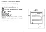
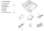
Page 4: ...SECTION 1 ...

Page 5: ...osive gas Level Well ventilated air turnover at least three times per hour Not subject to vibration Dust free Condensation free Temperature 17 to 28 C Humidity 30 to 85 RH Away from other electronic equipment to avoid in terference Away from heaters and air conditioners to avoid sudden changes of temperature With clearance as shown below 1 1 ...

Page 6: ...1 2 UNPACKING PROCEDURE 1 Pull the machine out of the carton with the foam supports and package 2 Remove the package the foam supports and the plastic bag from the machine 1 2 ...

Page 7: ...1 3 ACCESSORIES 1 Facsimile Terminal 1 2 Thermal Paper 15m 3 Operation Manual 1 4 Power Cord 1 5 Tilt Stand 1 6 Screwdriver 1 7 One touch Key Labels 1 set 1 3 ...

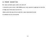
Page 8: ...SECTION 2 ...

Page 9: ...onal as the tilt stand does not have to be used 1 2 3 Remove all tape from the outside of the machine Push down the printer cover release button A and open the print er cover Remove the red spacers from the platen roller bushings 2 1 ...

Page 10: ...dge feeding as shown below 5 Close the printer cover Ensure that the cover is locked properly Make a test copy 6 Stand the unit on its right side Attach the tilt stand to the rear base of the unit as shown two screws Then stand the unit back on its base 2 2 ...

Page 11: ... unit is off 1 Connect the power cord to a 230V 50 60Hz power source capable of supplying more than 10A 2 Voltage must not fluctuate more than 10 3 Make sure that the plug is firmly inserted into a proper grounded wall socket 4 A dedicated circuit is recommended 2 3 ...

Page 12: ...SECTION 3 ...

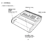
Page 13: ...3 1 EXTERNAL Guide to Components 3 1 ...

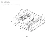
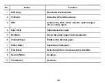
Page 14: ...3 2 INTERNAL Optical and Mechanical Components 3 2 ...

Page 15: ...onverts optical images into an analog signal 4 Paper Roll Thermosensitive paper 5 Rx Motor Drives the printer paper feed mechanism 6 Thermal Head Prints on the thermal paper 7 Platen Roller Feeds the printer paper 8 First Mirror Reflects light from the document to the SBU 9 Second Mirror As above 10 Third Mirror As above 3 3 ...

Page 16: ... Electronic Components 3 4 ...

Page 17: ...nsor SB 1 Detects when a document is set in the DF 5 Tx Motor Drives the DF and the scanner 6 SBU Converts optical images into an analog signal Monitors the telephone line Prints on the thermal paper Drives the printer paper feed mechanism 10 Printer Cover Sensor Detects when the printer cover is open and cuts SB 10 off the main power 11 PSU Supplies power to all parts 3 5 ...

Page 18: ...No Name Function 12 FCU Controls the system 14 Paper End Sensor Detects when the paper roll has run out SB 4 15 NIF Contains the network control hardware 3 6 ...

Page 19: ...SECTION 4 ...

Page 20: ...icator Voice Request Key Function Press to enter the programming mode Lights when a transmission failure document misfeed or copy misfeed occurs Lights when the unit is in TEL mode During communication press this key to request voice contact with the other terminal s operator 4 1 ...

Page 21: ...pad acts as a conventional numeric keypad When the Speed Dial lamp is lit this keypad can be used to enter a two digit Speed Dial code Push to enter a Speed Dial Code Push to clear the previously entered character or use as a cursor i Push to insert a pause in the telephone number ii Push to redial the remote terminal immediately Lights when the unit is ready to operate Press to select the require...

Page 22: ...l RTI TTl CSl ID code Date and time One touch Keys Speed dial numbers Up to 90 FAX TEL setting Local terminal telephone type Closed network enable disable Auto answer Delay time 2 Refer to the Operation Manual for details 1 CSI is programmed by user mode function no 64 and service mode function no 99 in European models 2 This function is service mode in European models function no 80 4 3 ...

Page 23: ...Enabling Quick Dial Programming ID Code Programming RTI Programming TTI Programming This function is in the service mode function no 80 Default setting is disabled in the German version This function is made available by changing bit SW 18 bit nos 5 and 6 This function is available only when bit SW 18 bit no 3 is O default setting is 1 except the UK version If this bit is 1 this function is enable...

Page 24: ...o select either automatic or manual reception Press to select FAX and to select TEL To select the time delay for answering the line in FAX mode Press to decrement and to select TEL To enter the date and time To enable or disable closed network transmission and reception Increment with decrement with and move the cursor with Clear For each feature press to enable and to disabled If enebled the remo...

Page 25: ... enable and to disable copies at the remote terminal 4 55 To match the unit s dialing mode Press for DTMF and for pulse dialing with the connected line This function is available only for the UK version in Europe The other versions can be enabled by the Function number 81 in the service man mode 54 56 To adjust the speaker volume Increase with and decrease with 55 57 To enable transmission report ...

Page 26: ...nication To program the Transmitting Terminal Identifier This is printed on the top of pages received at the remote terminal To program the Called Subscriber Identifier This is used in place of the RTI when communicating with a non Ricoh machine Enter the required code at the keypad Do not use 0000 or FFFF Enter the identifier from the left Increment the character at the cursor through the charact...

Page 27: ...Europe No 70 71 Asia No Purpose 70 To print the Transaction Confir tion Report 71 I To print the Telephone Lists Remarks There are two lists One touch Keys Speed Dial Codes 4 8 ...

Page 28: ...ss 1 4 7 and simultaneously Note If you cannot enter service mode install jumper 4 on the FCU before entering the service mode Europe only To exit the service mode press 3 6 9 and simultaneously Note Take out FCU jumper 4 if you do not wish the user to access service mode Europe only 4 9 ...

Page 29: ...rogramming ROM RAM display RAM rewriting System Report ROM RAM data printout Error code display Service Report CCITT and Maker code programming Thermal head parameter programming NCU parameter programming CSI Programming Remarks Europe only Europe only Local terminal only CCITT 0000 Maker 25 Enter the pulse width Europe only 4 10 ...

Page 30: ...from O to 42 seconds A high value would give you a chance to answer the telephone personally even if the unit is in Fax mode This setting has no effect on the way the machine operates in Tel mode in Tel mode the unit will never answer the line automatically 1 Press the Function key and enter 80 2 Press Yes 3 Either Press to decrement the time Or Press to increment the time 4 Press the Function key...

Page 31: ...nly affects the auto dialer inside the unit Service Mode I User Mode 1 Press the Function key and enter 81 M O D E N O 8 1 Y N S E L E C T P D D T M F 2 Press Yes 3 Either To specify dial tone press Or To specify pulse dialing press 4 Press Function to return to standby 1 Press the Function key and enter 4 The Current Status I I I I I 2 Either To specify dial tone press Or To specify pulse dialing...

Page 32: ...FAULT 0110 0000 BITSW 0 0110 0000 3 Make your changes Press to increment the bit switch number press to decrement Hold down for fast increment decrement Example Press once DEFAULT 0111 0100 BITSW 1 0111 0100 Press the numeric keypad key corresponding to the bit that you want to change Bits are numbered from 7 at the left to 0 at the right Example Change bit 0 to 1 Press 0 DEFAULT 0111 0100 BITSW 1...

Page 33: ...d consult a senior technician before changing any set ting 4 ROM and RAM display RAM rewriting Consult a senior technician before changing any RAM data 1 Press the Function key and enter 91 MODE NO 91 DISPLAY ROM RAM 2 Press Yes ADDRESS 0 0 0 0 DATA 0 3 3 Select the address Use the Clear key as a cursor Use to increment the cursor character Use the key to decrement 4 14 ...

Page 34: ...ts you from changing ROM areas 5 Either Change more addresses go back to step 3 Or Press the Function key to return to standby Useful RAM Addresses Contrast Thresholds Light 12C4 Normal 12C5 Dark 12C6 Sensor Threshold SB 4 in standby mode 1E84 40 Current Sensor Values SB 4 1E82 Number of Redials 1E6A Redialing Interval 1E6B 4 15 ...

Page 35: ...opy key to print the report PRINT SYSTEM REPORT 6 ROM and RAM Printout 1 Press the Function key and enter 93 MODE NO 93 Y N PRINT ROM RAM DATA 2 Press Yes PRINT DATA COPY N START 0000 END 0000 3 Enter the start and end addresses Use to increment to decrement and Clear to shift the cursor PRINT DATA COPY N START 1230 END 123F 4 Press Copy PRINT ROM RAM DATA 4 16 ...

Page 36: ...s Yes ERROR CODE 1 01 1 02 2 03 2 02 3 Either Press to display the next four codes Note If is pressed more than 7 times the machine returns to standby Or Press the Function key to return to standby 8 Service Report 1 Press the Function key and enter 95 MODE NO 95 COPY N FOR SERVICE REPORT 2 Press Copy The machine automatically returns to standby PRINT SERVICE REPORT 4 17 ...

Page 37: ...REMOTE TERMINAL MODE ERROR CODE S IDENTIFICATION RICOH FACSIMILE QA G3DR 0 23 RICOH 882 2176 G3ST 0 07 RICOH SVC O SEAS G3DT 0 07 WYWY MALAYSIA G3ST 0 08 0 07 0 00 0 00 0 00 1 21 1 21 0 04 0 01 0 00 0 00 0 00 0 00 1 21 0 23 1 21 0 62 0 06 1 71 1 71 1 71 The Error Code column lists communication errors The Error Code List area gives all types of error codes the most recent 32 codes only 4 18 ...

Page 38: ...AKER 2 Press Yes CCITT MAKER 0001 25 3 Enter the correct codes CCITT 0000 MAKER 25 Use to increment to decrement and the Clear key as a cursor key CCITT MAKER 0000 25 If incorrect codes are programmed communication using NSF S is disabled 4 Press the Function key to return to standby 4 19 ...

Page 39: ...d or FCU 1 Press the Function key and enter 97 MODE NO 97 SET PULSE WIDTH Y N 2 Press Yes PULSE WIDTH HEAD 1 00MS A 3 Enter the pulse shown on the thermal head e g 1 45 ins PULSE WIDTH HEAD 1 45MS A Enter the value directly at the keypad 4 Press the Function key to return to standby 4 20 ...

Page 40: ...U PARAMETER KPAD Y NO 00 065 Param NO Value 3 Change the value of the displayed parameter if required Enter the new value at the keypad NCU PARAMETER KPAD Y NO 00 075 4 Go on to change another parameter Press Yes until the desired parameter is displayed NCU PARAMETER KPAD Y NO 01 128 5 Press the Function key to return to standby after finishing A table of parameters follows 4 21 ...

Page 41: ...the first ring Undetected part of the second and subsequent rings Reset time Time between the closing of relay DS and the opening of relay DI TO Time that relay DI is open T1 Time that relay DI is closed T2 Time between the final closure of relay DI and the opening of relay DS T3 Formula N times N x 20 ms N x 20 ms N x 40 ms N x 1 ms N x 1 ms N x 1 ms N x 1 ms Factory Setting UK universal 75 128 5...

Page 42: ...s 1 2 3 4 Formula N x 20 ms N x 20 ms N x 1 ms N x 1 ms 15 N Factory Setting UK Universal 30 33 100 100 09 Asia 36 101 100 110 09 The above pulse dialing times T0 T1 T2 T3 are the values for 10 pps Times for 20 pps are half those for 10 pps DS relay control should be done for the Europe type NCU which has a ground start selection The first ring may not be detected until Parameter 05 Ringing Signal...

Page 43: ...er 99 2 Press Yes 3 Enter the required CSI using up to 20 numerals and spaces Using your telephone number is recommended Use digits 0 9 at the keypad Press Pause Redial to enter a space Press Clear to leave the character at the cursor unchanged Enter after the last digit of the CSI Example 213 555 9432 Press Yes to store this CSI The unit returns to standby 4 24 ...

Page 44: ...hen ENABLE SERVICE FUNC is displayed press the Start key immediately The following will appear D LED S LCD T F MDM VOICE SEN TEL DTMF The meaning of this display is as follows Light the Detail LED to select LED array lighting Light Standard to test the operation panel Press Yes True False to test the modem Light Voice Request to initialize the sensors Light Speed Dial to make a tone test 3 Make th...

Page 45: ...light It will remain lit for 8 minutes 3 Press Stop to return to standby 3 Operation Panel Test 1 Make sure that the Speed Dial and Voice Request LEDs are off 2 Select standard resolution then press Start The LEDs should be lit except for the following indicators which should be blinking Tel mode Caution LCD ALL DISPLAY 3 Press the Stop key to return to standby 4 26 ...

Page 46: ...TEST 3 Press the required keys to test the desired signal refer to the following table Example 9600 bps press and hold the start key then immediately press 9 MODEM TEST 9600 BPS Note The machine will return to standby after 8 minutes of testing any one tone 4 Press Stop to return to step 3 MODEM TEST 5 Press Stop once more to return to standby 4 27 ...

Page 47: ...0 bps 4800 bps 2400 bps 300 bps 2100 Hz CED 1850Hz 1650Hz 1100HZ 462 Hz 2100Hz G2 video signal Operation Press the following keys in sequence Start 9 Start 7 Start 4 Start 2 Start 3 copy 2 copy 8 copy 6 copy 1 copy 4 Copy Pause Redial 4 28 ...

Page 48: ...displayed the sensors are all in good order and have been automatically initialized 6 Tone Tests 1 2 3 4 Press the Speed Dial key then press Start DTMF TONE Press the key corresponding to the desired tone refer to the table given below Example 697 Hz push A DTMF TONE 697HZ Note The machine will return to standby if no key is pushed for 8 minutes Press Stop after testing this tone DTMF TONE Either ...

Page 49: ...one 9 Dual tone Push0 Push 1 Push 2 Push 3 Push 4 Push 5 Push 6 Push 7 Push 8 Push 9 Push Dual tone Push Tone Single tone 697 Hz Single tone 770 Hz Single tone 852 Hz Single tone 941 Hz Single tone 1209 Hz Single tone 1336 Hz Single tone 1477 Hz Single tone 1633 Hz Operation Push A PushB PushC PushD PushE PushF PushG PushH 4 3 0 ...

Page 50: ...hen immediately press a specified key depending on the desired printout Do not release the keys until the printer has started Thin closely spaced lines Copy key 1 Thick vertical stripes Copy key 2 Pattern Copy key 3 Dense diagonal stripes Copy key 4 Closely spaced horizontal lines Copy key 5 4 31 ...

Page 51: ... A and B must be as follows A4 or larger Less than 1 of the document length Smaller than A4 Less than 3 of the document length Clean the RI and R2 rollers Copy an R1 test chart using standard resolution Check the characters in frame F No characters must be missing in the subscan direction Check and adjust the following Flatness Reduction rate M T F Refer to section 6 1 for details 4 Make another c...

Page 52: ...Paper Leading Edge 4 3 3 ...

Page 53: ...tion 5 Communication Tests No Procedure Check Items I I 1 Call a remote unit and send 2 test charts 1 Resolution selection one in standard and the other in detailed 2 RTI display resolution 3 Voice request function 2 Receive 2 test charts 1 RTI display 2 Copy quality 3 Automatic reception function 4 Voice request function 4 34 ...

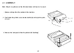
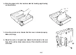
Page 54: ...SECTION 5 REMOVAL AND REPLACEMENT ...

Page 55: ...r 2 Remove the four screws holding the cover and ease off the cover 5 1 2 Printer Cover 1 Open the printer 2 Remove the printer each end cover four screws two at Note When replacing the cover make sure the harness on the right end is in the harness clamps that two 5 1 ...

Page 56: ...3 Operation Panel 1 Remove the top cover see section 5 1 1 2 Remove the ground wire one screw 3 Remove the E ring 4 Slide the operation panel to the left along the hinge pins and remove it one connector 5 2 ...

Page 57: ...e section 5 1 3 Remove the scanner guide plate A two screws Remove the RI roller B one E ring and bushing on the right hand side Remove the LED array assembly C two one connector on the FCU Remove the LED array from the bracket screws Connect up a new LED array and test it using array test procedure see page 4 26 screws four the LED 5 3 ...

Page 58: ...irst push the gear and bushing on the left end of the shaft as far left as they will go Then 1 Fit the resulting clearance D into the slot E in the bracket 2 Push the shaft in the direction of the arrow until the bushing fits into the slot E When replacing the scanner guide plate fit the two tabs on the rear F into the slots G in the upright brackets 5 4 ...

Page 59: ...he scanner guide plate two screws see section 5 2 1 step 3 4 Remove the R1 roller one E ring and one bushing see section 5 2 1 step 4 5 Remove the R2 roller in the same way as the R1 roller 6 Disconnect the LED array CN11 and the SBU CN7 from the FCU 7 Remove the four screws that hold the scanner unit to the base 5 5 ...

Page 60: ... out the scanner unit Reassemble Make sure that there are no wires obstructing the holes for the scanner unit securing screws Make a copy of a test chart There should be no need for any scanner adjustments 5 6 ...

Page 61: ...ove the NIF three screws two connectors 3 Remove the bracket that is on top of the PSU four screws 4 Remove the PSU two screws two connectors 5 3 3 OP PORT 1 Remove the operation panel see section 5 1 3 2 Remove the upper scanner guide plate four screws feeding the ground wire through the opening in the plate 3 Remove the OP PORT PCB 12 screws 3 connectors 5 7 ...

Page 62: ... RAM changes have been made since installation 3 Note the settings of functions 3 4 51 54 55 56 and 57 Asia Note the settings of functions 3 4 81 53 54 55 56 and 80 Europe 4 Make sure that SW1 battery switch and SW2 factory use only of the new FCU are ON closed Removal 1 Remove the scanner unit see section 5 2 2 2 Remove the FCU ten connectors one screw Note The harnesses are not marked Take care ...

Page 63: ...void static electricity because Bi CMOS LSIs are used Pack the thermal head in an anti static bag 2 Clean the heating element surface with alcohol soaked guaze or soft cloth This prevents irregular density and white blanks due to damaged or stained heating elements 3 Do not hit or rub the heating element board surface with a sharp edge or hard material 4 Check that the head is positioned properly ...

Page 64: ... top cover see section 5 1 1 2 Remove the modem see section 5 3 1 3 Open the printer and take out the paper roll 4 Remove the paper guide A two screws 5 Remove the E ring B on the left end of the printer cover lock shaft 5 10 ...

Page 65: ...ad two screws two connectors 9 Install a new thermal head Note Do not touch the heating elements Read the precautions at the beginning of this procedure 10 Reassemble To replace the lock lever shaft i Place the left hand end of the shaft into the opening E ii Replace the right hand end of the shaft into its original position iii Replace the left hand end into its original position iv Replace the s...

Page 66: ... to 7 of the thermal head removal procedure see section 5 3 5 2 Remove the SBU two screws 3 After installing a new SBU carry out the SBU adjustment procedures 5 4 SENSORS After replacing SB 4 initialize the sensors see page 4 29 5 12 ...

Page 67: ...SECTION 6 ...

Page 68: ... pattern of the test chart at the scan line position 2 Loosen the lens securing screw 3 Move the lens back and forth until B is maximised Test point XVIDEO 4 Tighten the lens securing screw Standard B A X 100 Tools Symptoms Oscilloscope Blurred Allen keys characters Test chart R1 Philips screwdriver Remarks I 6 1 ...

Page 69: ...ft and move it back and forth until the XVIDEO signal has 6 or fewer crosspoints 4 Tighten the lens block securing screws 1 Set the adjustment knobs as shown below 2 Loosen the SBU securing screws Standard e g 6 crosspoints Tools Symptoms Oscilloscope Philips screwdriver Test chart R1 Blurred or filled in characters Oscilloscope Philips screwdriver Scan line test strip Adjustment knobs Uneven dens...

Page 70: ...waveform with the adjusting knobs until it is as shown on the right 6 Adjust VR1 on the SBU until XVIDEO within the standard limit 7 Gently tap the SBU until its position is correct 8 Tighten the SBU securing screws 9 Take out the adjustment knobs 10 Go onto the Error bits procedures Standard Tools Symptoms Remarks If flatness is out Of spec clean mirrors or change LED array 6 3 ...

Page 71: ...nsure that there are no abnormal peaks in the XVIDEO waveform Standard No abnormal peaks Tools Test chart oscilloscope 0 2 V div 0 5ms div Abnormal Replace lines along the SBU if prints made error bits by the copy are visible key 6 4 ...

Page 72: ...Remove the top cover 2 Check that the clearance A is correct 3 If necessary adjust by loosening the screw B and moving the bracket Standard T 0 4 0 5mm with cover closed Tools Philips screwdriver clearance gauge Symptoms Printer error Remarks 6 5 ...

Page 73: ...6 3 OPERATION PANEL 1 LCD Brightness VR1 can be used to adjust the LCD brightness It alters the resistance between the 5V input from the FCU and the VLCD pin of the OPP LSI 6 6 ...

Page 74: ...SECTION 7 ...

Page 75: ... and R2 Incremental Rollers b R1 and R2 Pressure Rollers c S1 and S2 Sensors 2 Printer Unit Item to be cleaned a Thermal Head b Platen Roller C SB 4 Material to be used Soft cloth water Soft cloth water Blower brush Material to be used Soft cloth alcohol Soft cloth alcohol Blower brush 7 3 PERFORMANCE CHECKS Perform the quality checks listed on page 4 32 7 1 ...

Page 76: ...a White level output b Flatness c Error bits Refer to section 6 1 for details 2 Position the 8 line mm pattern of the R21 test chart at the scan line Check the output waveforms at CN8 2 and CN8 3 of the FCU for the following procedures a Reduction rate b MTF focusing 7 5 LINE CONNECTION CHECK Check 1 Ground connection 2 Telephone and line connection 7 6 OTHERS Check the supply of consumables on th...

Page 77: ...SECTION 8 T R O U B LE S H O O T I N G ...

Page 78: ...m remote unit after MODEM training Suggested Cause Action 1 Check all connections inside the machine 2 Replace the FCU 3 Replace the modem 4 Measure the Rx signal level 5 Check the received signal on an oscilloscope 6 Incompatible remote terminal 1 Check remote terminal for printer failure jam or empty roll or if operator pushed Stop Check the remote terminal Example 1850 1000 800 2 Check the remo...

Page 79: ...e failed after 3rd try Suggested Cause Action 2 Check the Tx signal level 3 Check for line problems 2 Check the remote terminal 3 Check the Tx signal level 4 Incompatible remote terminal 5 Check for line problems 2 Line was disconnected 1 Check the Tx signal level 3 Defective modem at either end 4 Check for line problems and noise 5 Rx signal at either end too weak or too strong 6 Check line conne...

Page 80: ...uld not be recognized 2 Check the remote terminal 0 10 As for 0 08 but error report disabled As for 0 08 0 11 Error code memory overflow when 1 Check for printer jam or roll end printer failed 0 12 After sending at 2400 bps RTN As for 0 08 was detected I I 8 3 ...

Page 81: ...ing EOL not detected within 5 seconds of the previous EOL Modem carrier dropped for 200ms or more while receiving image information 1 As for 0 20 2 Check for line noise 3 Disconnected line 4 Check remote FCU is faulty 1 As for 0 20 2 Replace the NCU 3 Check the remote terminal 4 Check for line problems 5 Remote terminal modem faulty 0 23 Line errors have exceeded the limit 1 As for 0 20 2 Measure ...

Page 82: ...ggested Cause Action 1 As for 0 20 2 Measure the Tx signal level 3 Incompatible remote terminal 1 As for 0 20 2 Incompatible or defective remote terminal 3 Check MCF CFR signal turn off timing 1 Check all connections inside the machine 2 Check with the operator whether operator call tone sounded 3 Faulty stop key 4 Check whether operator call is working If not replace FCU 5 If no ACK NAK tones on ...

Page 83: ... for 0 60 3 seconds 2 Incompatible or defective remote terminal Phasing failed 1 As for 0 61 2 Try to receive from another G2 unit Black line sync signal longer than expected EOM not detected within 3 seconds EOM carrier not dropped within 5 seconds 1 As for 0 62 1 As for 0 20 2 Defective remote terminal 3 Check whether EOM signal comes in 2 Incompatible or defective remote terminal 3 Check EOM si...

Page 84: ...munication Code 0 70 Meaning Communication modes unmatched Suggested Cause Action 1 Check all connections inside the machine 2 Replace the FCU 3 Replace the modem 4 Check what mode is selected at remote terminal 8 7 ...

Page 85: ... was pulled out prematurely copy Suggested Cause Action 1 Improperly inserted document 2 Misadjusted or faulty sensors 3 Replace FCU 4 Replace Tx motor 5 Check all connectors inside machine 6 Document length exceeded maximum 7 Check document feed condition 1 Check all connectors inside machine 2 Replace the FCU 3 Check SB1 4 Check whether a document is actually jammed 1 As for 1 10 2 Check SB2 3 C...

Page 86: ...s set when a jam condition existed Document jammed when feeding out Suggested Cause Action 1 As for 1 00 1 Replace the FCU 2 Check SB2 3 Scanner feedout path blocked 4 Document length exceeded maximum 5 Check document feed condition 8 9 ...

Page 87: ...tion 1 20 Paper jammed during receiving Paper jammed after printing 1 Replace the FCU 2 Check all connectors inside machine 3 Paper path obstructed 4 Copy tray overloaded 5 Check whether paper is actually jammed 6 Check that paper feed operation is normal 8 10 ...

Page 88: ...ding Suggested Cause Action 1 As for 1 20 items 1 and 2 2 Check SB4 3 Paper ran out 1 50 1 51 1 71 Thermal head error during reception Thermal head error during copying Cover opened during printing 1 As for 1 20 items 1 and 2 2 Replace thermal head 1 Check all connections inside machine 2 Check whether operator opened covers 3 Check cover switch position and action 8 11 ...

Page 89: ...state 1 Check modem FCU connection 2 11 Rx data transfer clock not output 2 Replace FCU 2 12 Tx data transfer clock not output 3 Replace modem 2 20 No data compression 1 Check all connections inside machine 2 21 Data compression not completed 2 Replace FCU 2 22 A scan line needed more than 10s for compression 2 25 No phasing signal 2 26 Data not sent out 8 12 ...

Page 90: ...es for more than 6s Has signal dropout less than 200ms Incoming carrier continues for more than 6s 2 40 Abnormality after interrupt signal 2 41 Abnormality when FCU receives OP PORT data 2 42 Abnormality after operator adjusted clock Suggested Cause Action 1 As for 2 20 2 Replace modem 3 Check the line condition 1 As for 2 20 2 Replace OP PORT 8 13 ...

Page 91: ... Broken Tx motor Faulty FCU board Misfeed or Skew Dirty R1 or R2 roller clean with a soft cloth and water increment roller or alcohol pressure roller Soiled Document Dirty R1 or R2 roller clean with a soft cloth and water increment roller or alcohol pressure roller 8 14 ...

Page 92: ...d 3 Copy Quality 1 Received Copies If there is no fault in the transmitting terminal or on the line but the copy quality is bad either Check that the printer cover is closed properly Check the thermal head pulse width Clean the thermal head soft cloth If the output continually appears to be stretched Check the Rx timing belts 8 15 ...

Page 93: ...lean with a soft cloth 3 Old or dirty LED array 3 Clean or replace Magnification I Check the reduction rate I See section 6 1 Blurred Characters 1 Focusing needs adjusting 1 See section 6 1 2 Reduction rate needs adjusting 2 As above Filled in Characters 1 Reduction rate needs adjusting 1 As above Side to Side 1 Scan starting position needs 1 As above Registration Error adjusting Output too Light ...

Page 94: ...3 Effects of line problems on copy quality 1 Missing lines shrinkage in sub scan direction Original 2 cutoff Bad copy sample Bad copy sample Some lines may be missing just before the cut off 8 17 ...

Page 95: ......

Page 96: ......

Page 97: ......

Page 98: ......

Page 99: ......

Page 100: ......

Page 101: ......

Page 102: ......

Page 103: ......

Page 104: ......

Page 105: ......

Page 106: ...A H ...

Page 107: ... 0 0 0 0 0 0 1 1 0 0 0 0 0 1 1 0 0 0 0 0 0 0 0 0 0 0 0 1 0 0 1 0 Bit Switch OD OE OF 10 11 12 13 14 15 16 17 18 19 1A 1B 1C 1D 1E 1F A 1 7 6 5 4 0 0 0 1 0 1 0 1 1 1 0 0 1 0 0 0 0 0 0 1 0 0 0 0 1 1 1 1 1 1 0 0 1 0 1 0 1 0 0 0 0 0 0 0 0 0 0 0 0 0 1 1 0 0 0 0 0 0 0 0 0 0 0 0 0 0 0 0 0 0 0 0 0 0 0 0 Bits 3 2 1 0 0 0 0 1 1 0 0 1 0 0 0 0 0 1 1 0 0 0 1 0 0 0 0 0 1 1 1 1 0 0 1 0 0 0 0 0 0 0 0 1 0 0 0 1 1 ...

Page 108: ...0 0 0 1 1 0 0 0 0 0 1 1 0 0 0 0 0 0 0 0 0 0 0 0 1 0 0 1 0 Bit Switch OD OE OF 10 11 12 13 14 15 16 17 18 19 1A 1B 1C 1D 1E 1F A 2 Bits 7 6 5 4 0 0 0 1 0 1 0 1 1 1 0 0 1 0 0 0 0 0 0 0 1 0 0 0 1 1 1 1 1 1 0 0 1 0 1 0 1 0 0 0 0 0 0 0 0 0 0 0 0 0 1 1 0 0 0 0 0 0 0 0 0 0 0 0 0 0 0 0 0 0 0 0 0 0 0 0 3 2 1 0 0 0 0 0 1 1 0 0 0 0 0 0 0 1 1 0 0 0 1 0 0 0 0 0 1 1 1 1 0 0 1 0 0 0 0 0 0 0 0 1 0 0 0 1 1 0 0 0 1...

Page 109: ...g function 51 to enable Closed Network Transmission 1 Same as for bit 3 above but for Closed Network Reception To directly connect two machines and check the communication function This bit should be O when RAM data is to be changed from the service center by a K10 series machine If the unit often receives messages from devices that do not respond quickly to CFR set this to 1 Some PCs with fax boa...

Page 110: ...cating in Gill mode the communication parameters are displayed as follows 96 s 1D AN DCS I0M Modem rate Resolution Coding Size Mode I 0 rate 96 9600 bps S Standard 1D MH A A4 DCS CCITT 10M 10ms line 72 7200 bps D Detail N No reduction Standard mode 20M 20ms line 48 4800 bps NSS Non standard 40M 40ms line 24 2400 bps mode RICOH A 4 ...

Page 111: ... at power up 0 Standard 1 Detail Standby default resolution 1 As specified in bit 1 When communication is finished the resolution returns to that selected by bit No 1 if this bit is 1 Original contrast selection at power up The original contrast selected by these bits is selected also when transmission is completed Remarks Set as the customer desires Changed by function 1 A 5 ...

Page 112: ... standby default mode 0 Speed Dial 1 Keypad When communication is finished the keypad mode is selected if this bit is 1 6 Contrast selection reset 0 Contrast does not reset after the end of transmission 1 AS specified in bits 3 and 4 7 Not used A 6 ...

Page 113: ...times as fast as the standard mode 1 The same speed as the standard mode Not used Recognition of remote terminal s paper length 0 No limit is recognized 1 Limit is recognized MPS is sent after receiving the length specified by remote terminal The remote terminal may designate a fixed paper length such as A4 or B4 Remarks Select to meet the line condition Keep at 1 A 7 ...

Page 114: ...ission level from modem 0 1 d B 1 0dB 0 2 d B 1 0dB 0 4 d B 1 0dB 0 8 d B 1 0dB Not used Handshake modern rate for protocol when transmitting Remarks To change the transmission level The Tx level is the sum of these 4 bits Keep at 0 0 Keep at 0 0 A 8 ...

Page 115: ... received it is ignored CNG signal transmission in manual transmission mode O Enabled For automatic dialing this bit should be 0 DIS detection times Echo countermeasure for transmission 0 Once 1 Twice Not used Remarks If this is set to 1 the machine will dis connect instead of ignoring echoes If this is set to 1 the machine waits for a second DIS before returning DCS Keep at 0 0 A 9 ...

Page 116: ...ndition of TCR 0 Results of communications which were disconnected before transmission reception of image data are not printed 1 All communications are listed except for telephone calls On hook Dial 7 NCU type 0 PROGRAMMABLE 1 PERMISSIVE A 10 ...

Page 117: ...I frame display decision 0 Displays the frame with priority 1 Displays both frames NSF CSI and or CSI frame display decision 0 Displayed When this bit is 1 bits O and 1 are ignored NSF frame reception 0 Enabled Transmission of the TSI frame before the DCS code 0 Enabled Transmission of the NSS TSI frame after NSS S code 0 Enabled GI Group Identification signal reception in G2 mode 0 Enabled Not us...

Page 118: ...ge signal if the page takes longer than 8 minutes to transmit The receiver outputs the rest of the page on a separate sheet Not used Not used Not used Conditions for going into transmit mode 0 After detecting polarity change and CED 1 Goes into Tx mode after detecting any frame Remarks Keep at 1 Keep at 1 FTZ specification Keep at 1 A 12 ...

Page 119: ...led When a line error occurs the error counter increases by 1 When the counter reaches 10 RTN is sent New FTZ Quality Criterion Threshold value for line error New FTZ Quality Criterion Error Ratio Error Lines Total Line 100 Not used Remarks Values for detailed resolution are in parenthesis In the new FTZ quality check the error line counter wiII be decremented by one every time an error free line ...

Page 120: ...gth Not used Modem types to be notified to the transmitting terminal Receiver training error counter method 0 Standard 1 For Europe Receiver training error tolerance Standard Europe A 1 4 Remarks Set this to 1 when the user requires all received copies to be marked into A4 lengths Keep at 1 ...

Page 121: ...andard and 7 7 Detail 1 3 85 only Handshake modem rate for protocol when receiving Modem rate for the start of reception I O rate in standard mode for reception I O rate in detail mode for reception 0 Two times as fast as the standard mode 1 The same speed as the standard mode Remarks Keep at 0 0 A 15 ...

Page 122: ...n Remarks o Transmission of NSF S frame 0 Enabled 1 Transmission of NSF CSI frame 0 Enabled 2 Transmission of CSI frame 0 Enabled 3 Transmission of Group Identification signal 0 Enabled 4 5 Not used Keep at 1 6 7 Not used A 16 ...

Page 123: ...T No o 1 2 Function Remarks Not used I Keep at 1 Communication mode at power up 0 AUTO 1 G2 Compatibility with MV1200 1 Enabled 3 FTZ Specifications For Germany enables FTZ protocol 1 Enabled 4 5 6 Not used 7 A 17 ...

Page 124: ...peaker volume during transmission 1 2 3 I Not used 4 Monitor speaker during reception 1 Disabled at all times during reception Monitor speaker volume during reception 5 6 7 I Not used Remarks Changed by function 56 Asia Changed by function 54 Europe Changed by function 56 Asia Changed by function 54 Europe A 18 ...

Page 125: ...Not output automatically TCR memory cleared after output 1 TCR memory cleared TCR is cleared after a manual TCR Function 70 is performed TSI printing 0 Enabled When this bit is set at 0 the TSI or NSS TSI sent from the transmitter is printed at the head of the output data If this is enabled and if bit 3 of bit switch F is 1 the TSI will be printed on top of the TTI A 19 ...

Page 126: ...r erasing the bit is automatically set back to O Clearing of the transmit and receive counters scanned and plotted document counters 1 Clear When the stop button or function button is pressed or when the timer is exceeded after this bit is set at 1 the counters are cleared When they are cleared this bit is automatically set back to 0 RAM clear and reset After this bit is set to 1 the CPU resets th...

Page 127: ...Maximum transmittable document length Minimum printout length 0 75 mm 1 150 mm A5 length Not used Not used Not used Not used Monitor speaker status during video data communication 0 off 1 On Remarks 1 1 is not used Keep at 1 Keep at 1 Keep at 1 ...

Page 128: ...TI page number output 0 Transmitted 1 Not transmitted TTI printing start position This is the distance of the time date information in from the scan start position 0 2 4 m m 1 4 8 m m TTI printing during copying 0 Prohibited 1 Printed Buzzer volume during operator call for Voice Request Pause key input indication on display panel 0 P 1 Remarks A 22 ...

Page 129: ...end of a page before the unit returns to standby flags to the remote terminal 0 5 seconds normal 1 10 seconds 4 Error code printing in Error Report Keep at 1 in the German and Italian versions 0 Code is printed 1 Disabled 5 Use of Quick Dial Key J 0 As a normal Quick Dial Key 1 AS a TEL FAX change key 6 Operation panel type An optional operation panel without 0 Includes 10 one touch keys one touch...

Page 130: ...d Ireland Norway Sweden Switzerland Portugal Netherlands U S A Asia Japan 4 0 0 0 0 0 0 0 0 0 0 0 0 0 1 1 1 3 0 0 0 0 0 0 0 1 1 1 1 1 1 0 0 0 2 0 0 0 1 1 1 1 0 0 0 0 1 1 0 0 0 1 0 0 1 1 0 1 1 0 0 0 1 1 0 1 1 0 0 0 1 1 0 1 1 0 0 0 1 0 1 1 0 1 1 Not used Remarks For enabling the required set of PTT parameters Japan only A 24 ...

Page 131: ... BIT SW 11 Function 6 7 Dialing method from PABX to PSTN BIT NO 7 6 PSTN 0 0 Loop Start 0 1 Ground Start 1 0 Flash Start 1 1 Remarks A 25 ...

Page 132: ... Busy and ringback tone detection 0 Enabled 4 Line current detection 0 Enabled 5 6 Dial tone detection PABX 0 Enabled Redial when CCITT T1 timer exceeded 0 Enabled 1 Disabled for Austria and Norway 7 Dialing method 0 DTMF 1 PD Remarks Note that in P N mode 0 is 10 pulses Europe only Europe only Europe only Europe only Changed by function 55 Asia Changed by function 4 or 81 Europe A 26 ...

Page 133: ... to PSTN Access No Hex value of BITSW13 If the machine detects this access code at the start of a telephone number it will wait until PSTN dial tone is detected before continuing This function is only enabled when bit switch 11 bits 6 and 7 select Loop Start Remarks Example Code 0 A 27 ...

Page 134: ...BIT No o 1 2 3 4 5 6 7 Function Not used Dotted line page break indication 0 Printed 1 Disabled Not used Dial pulse rate for NCU auto dialer 0 20 pps 1 10pps Remarks A 28 ...

Page 135: ...BIT No o 1 2 3 4 5 6 7 Function Not used Factory use only Not used When the copy count is more than 20 in copy mode 0 Copy is disabled 1 Machine stops for 40 sec per 1 sheet Not used Remarks A 29 ...

Page 136: ...On hook dialing mode before and USA only after sending dial signals 0 Enabled Monitor speaker volume in On hook dialing mode before and after sending dial signals 1 2 4 1 G3 Rx disabled 5 1 G2 Tx disabled 6 1 G2 Rx disabled 7 On hook dial 0 Enabled USA only ...

Page 137: ...uto answer delay time BIT Time 6 12 18 24 30 36 42 48 54 60 seconds Three minute timer when in service mode 0 Enabled Thermal Head Type 0 Matsushita 1 Ricoh MTF 0 Enabled 1 Disabled Remarks Changed by function 4 Asia Changed by function 80 Europe Changed by function 4 Asia Changed by function 80 Europe A 31 ...

Page 138: ... function If this is set to 1 function 80 in 1 Disabled models will be disabled Closed Network Transmission If bits 5 and 6 are both set to 1 function 56 1 Disabled in European models will be completely disabled Keep at 1 in the German version Closed Network Reception Keep at 1 in the German version 1 Disabled CSI Programming If this is set to 1 function 64 in European models 0 User level 1 Servic...

Page 139: ... 1 2 3 4 5 6 7 Function Remarks Cable equalization in transmit mode 0 Enabled Cable equalization in transmit mode I Cable equalization in receive mode 0 Enabled Cable equalization in receive mode Not used A 33 ...

Page 140: ... 7 Function MPS timing 1 Resolution change 0 Flag transmission Operator call when Ready lamp blinks 1 Enabled 0 Disabled Redial when T1 time ran out 0 Enabled Not used Remarks Always disabled for Austria and Norway A 34 ...

Page 141: ...BIT No o 1 2 3 4 5 6 7 Function Detection time of 1300Hz Not used Remarks Japan and USA only A 35 ...

Page 142: ... BIT SW 1C BIT No o 1 2 3 4 5 6 7 Function Remarks Not used Not used A 36 ...

Page 143: ...B JUMPERS TEST POINTS AND VRs FCU VC1 Do not touch SW1 Battery switch keep ON during normal use SW2 Keep ON VR1 Tx level adjustment SBU VR1 White level adjustment TP1 XVIDEO OPU VR1 LCD brightness adjustment B 1 ...

Page 144: ...Notes 1 2 3 FCU jumper 4 S Service Mode Enabled S Short Blank Open FCU jumper 3 Norway return loss FCU jumper 2 Do not remove B 2 ...

Page 145: ...APPENDIX C POINT TO POINT DIAGRAM I C 1 ...

Page 146: ...APPENDIX D BLOCK DIAGRAMS 1 System Control D 1 ...

Page 147: ...2 Video Data Path Transmission D 2 ...

Page 148: ... Reception D 3 ...

Page 149: ... Copying D 4 ...

Page 150: ... Video Processing Circuit D 5 ...

Page 151: ...3 Communication Control D 6 ...

Page 152: ...4 Power Supply Distribution D 7 ...

Page 153: ... PSU D 8 ...

Page 154: ...APPENDIX E PCB LAYOUTS FCU 1 4 Parts Layout E 1 ...

Page 155: ...FCU 2 4 Parts Side E 2 ...

Page 156: ...FCU 3 4 Comp Side E 3 ...

Page 157: ...FCU 4 4 Reverse E 4 ...

Page 158: ...NIF 1 4 Parts Layout ...

Page 159: ...NIF 2 4 Parts Side E 6 ...

Page 160: ...NIF 3 4 Comp Side E 7 ...

Page 161: ...NIF 4 4 Reverse E 8 ...

Page 162: ...PSU 1 2 E 9 ...

Page 163: ...PSU 2 2 Reverse E 10 ...

Page 164: ...SBU 1 4 Parts Layout E 11 ...

Page 165: ...SBU 2 4 Parts Side E 12 ...

Page 166: ...SBU 3 4 ...

Page 167: ...SBU 4 4 Reverse E 14 ...

Page 168: ...ut L SB 1 Document sensor Photointerrupter Actuator No paper Paper SB 2 Scan line sensor Photointerrupter Actuator No paper Paper SB 4 Roll end sensor Reflective photosensor Paper No paper SB 10 Top cover switch Microswitch Cover open Cover closed F 1 ...

Page 169: ...lines FAX TEL Redialing twice at 5 min intervals immediate redial option On hook dial Built in phone Speed Dial codes up to 90 One touch keys single addresses G2 G3 autocompatibility Automatic fallback MTF correction Contrast selection Send Later transmission one destination Europe o o o o o x x o o o o o o o o Asia o o o o o x x o o o o o o o o Remarks ...

Page 170: ...og Closed Network Communication Reports Lists Automatic TCR Journal Transmission Report Error Report User initiated TCR Journal Telephone List Service Level Service Report Parameter List Memory Dump Europe o o o o o o o o o o o o o o Asia o o o o o o o o o o o o o o Remarks Note 1 Note 2 Note 3 G 2 ...

Page 171: ... K10 Europe o o o o o o o o o o o o o o o o o o o o Asia o o o o o o o o o o o o o o o o o o o o Remarks Note 4 Note 2 Note 5 Notes 1 Service level for Europe 2 Default setting is disabled for Germany This is made available by bit SW 18 bit nos 5 and 6 4 This can be selectable by both user level and service level for Europe Default setting is user level only for the UK and Universal versions 3 Ger...

Page 172: ...phone network Direct coupling Maximum 216 x 600 mm W x L Up to 14 m length available Minimum 148 x 105 mm W x L Thickness 0 05 to 0 15 mm Manual feed face down Flat bed CCD Main scan 8 pixels mm Sub scan 3 85 lines mm Standard 7 7 lines mm Detailed MH QAM PhM AM FM VSB FM Groups 2 and 3 Automatic compatibility 9600 7200 4800 2400 bps Automatic fallback 21s for one CCITT 1 test chart using standard...

Page 173: ... Power supply Maximum power consumption Weight Specifications Voltage 230 30 V ac Frequency 50 60 Hz single phase Standby 18 5W 240V Transmission 32 5W 240V Reception 29 5W 240V Copying 43 7W 240V 5 kg G 5 ...

Page 174: ... of the fax machine used for identification Disconnect A protocol signal sent by the transmitter to release the telephone line DCR DCS DIS DRAM DTMF EOM EOP EPROM Data Compressor Reconstructor A VLSI circuit used to compress and reconstruct data contained in the FCP Digital Command Signal a protocol signal that sets up Group 3 facsimile parameters Digital Identification Signal A protocol signal th...

Page 175: ... an indicator lamp Large Scale Integration A process of making micro chips MCF MH MPS MTF NIF NSF NSS Message Confirmation A protocol signal confirming reception of the previous page sent Modified Huff man A compression method used in facsimile to code scan lines Modified Huff man Coding is a one dimensional run length digital scheme of coding white and black runs Multipage Signal A protocol signa...

Page 176: ...Switched Telephone Network The normal telephone network used for voice communications PSU QAM RTI RTN RTP Power Supply Unit The assembly that supplies voltages to the required sections and components of the fax Quadrature Amplitude Modulation A modulation technique used when transmitting at 9600 and 7200 bps so that we can transmit over the PSTN Remote Terminal Identification The RTI is an alphanu...

Page 177: ... all fax transactions and shows date time RTI mode number of pages result and department code Transmit Terminal Identification An ID of the transmitter that is printed at the top of each page sent includes the date and time customer ID and page number Video Processing Peripheral A Ricoh custom LSI that processes and A D converts the CCD output video signal H 4 ...

Reviews: