

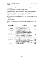


Details
Cross-reference
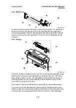
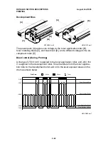
Group 3 Facsimile Manual, section 2-3
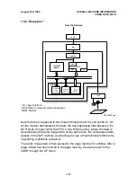
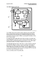
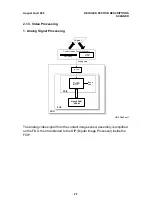
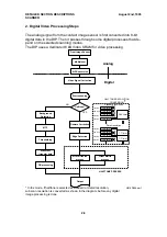
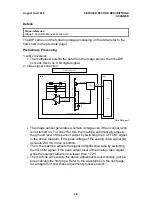
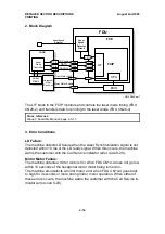
The DIP carries out the following image processing on the data (refer to the
flow chart on the previous page).
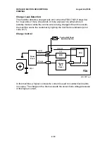
Preliminary Processing
1. A/D conversion
•
The multiplexer selects the data from the image sensor, then the DIP
converts this to an 8 bit digital signal.
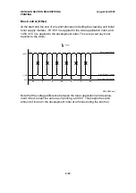
2. Video signal correction
•
The image sensor generates a certain voltage even if the scanner lamp
is not turned on. To correct for this, the machine automatically adjusts
the ground level of the sensor output by switching the VOFFCNT signal
in the above diagram, if the peak voltage of the analog video signal [B]
exceeds 234 mV in this condition.
•
Then, the machine adjusts the signal’s amplification ratio by switching
the VGCOM signal, if the peak output level of the analog video signal
while the scanner lamp is on is lower than 1.72V.
•
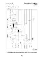
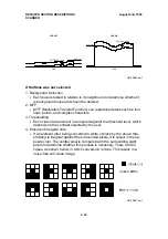
The machine will execute the above adjustments automatically, just be-
fore scanning the first page. Refer to the waveforms on the next page
for a diagram of how these adjustment processes work.
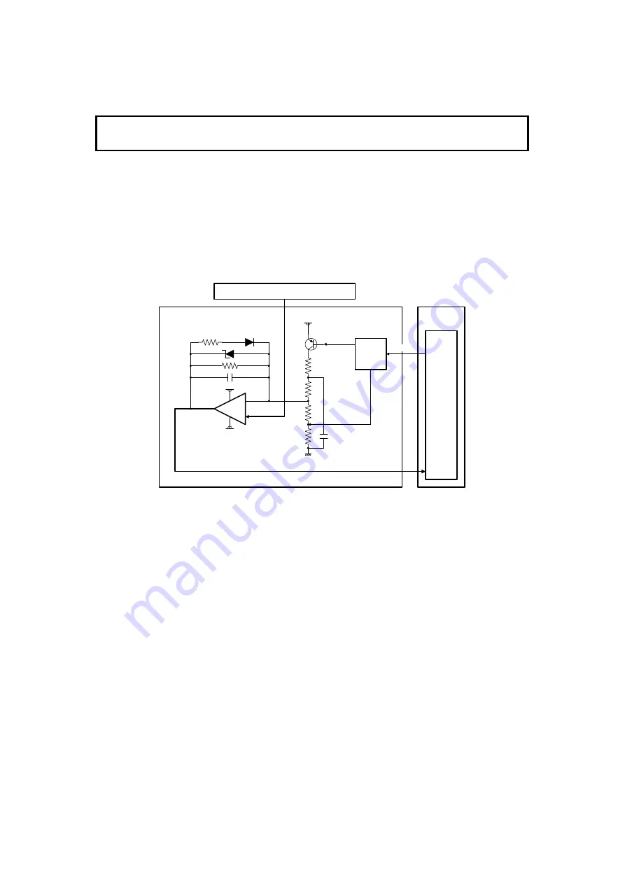
FCE
FDU
IC2
EXIO
VOFFCNT
VGCOM
FCIP
Serial I/F
Analog Video Signal [B]
Contact Image Sensor
Analog Video
Signal [A]
+5VV
ZD10
R38
C66
R123
R117
R13
D8
R12
R2
-5V
+5VV
C57
H516D564.wmf
August 2nd, 1995
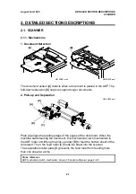
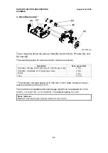
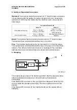
DETAILED SECTION DESCRIPTIONS
SCANNER
2-9


