


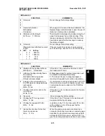
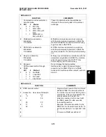


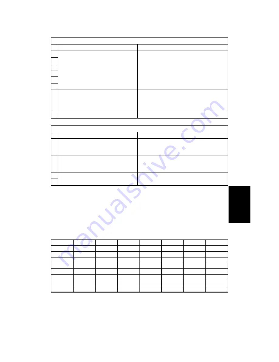
Bit Switch 0D
FUNCTION
COMMENTS
0
Not used
Do not change the factory settings.
1
2
3
4
5
6
Contents of the top line of the LCD
when handset mode is in use
0: Telephone number dialed
1: HANDSET MODE
0: The telephone number being dialed is
displayed.
1: Only HANDSET MODE is displayed.
7
Not used
Do not change the factory setting.
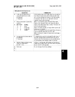
Bit Switch 0E
FUNCTION
COMMENTS
0
to
4
Not used
Do not change the factory settings.
5
Conditions for reception
0: Normal
1: RTI or CSI needed
1: If the sending machine does not transmit
an RTI or CSI, the call will be rejected, and
the machine will send DCN.
6
Not used
Do not change the factory settings.
7
Bit switches 0F to 1F are not used. Do not change any of the factory settings.
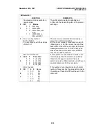
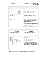
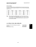
Factory Settings
The factory settings of all the bit switches are shown below in hexadecimal
code. The first digit represents bits 7 to 4, and the second digit represents
bits 3 to 0.
Switch
Setting
Switch
Setting
Switch
Setting
Switch
Setting
00
00
08
03
10
00
18
00
01
02
09
01
11
00
19
00
02
40
0A
03
12
00
1A
00
03
08
0B
00
13
00
1B
00
04
03
0C
00
14
00
1C
00
05
23
0D
00
15
00
1D
30
06
FF
0E
00
16
00
1E
01
07
06
0F
11
17
00
1F
85
4
SERVICE TABLES AND PROCEDURES
November 30th, 1991
BIT SWITCHES
4-19
Summary of Contents for FAX500
Page 1: ...FAX550 SERVICE MANUAL...


