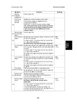
Mode No.
Function
Settings
83
Factory
Potential
Adjustment
Factory use only.
88
Total Copy
Counter
Display
Displays the total (electrical) copy counter.
The first three digits are displayed in the
magnification indicator.
Press the
*
key to view the last three digits.
The mechanical total counter and the electrical
total counter may not always display the same
value, because of initial differences in the
counter values.
90
Factory Data
and Counter
Clear
Factory use only.
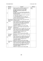
93
V
R
Correction
Reset
Resets the drum residual voltage correction counter
for the VR correction.
To clear, enter "1" then press the
key and the
*
key at the same time.
0: No
1: Yes
Use this mode only after installing a new drum.
94
V
L2
Correction
Reset
Resets the exposure lamp data and counter for the
V
L2
correction. Always perform this mode with SP95
as a set.
To Clear, enter "1" then press the
key and the
*
key at the same time.
0: No
1: Yes
Normally not needed in the field, as this is handled
by SP48.
95
V
L
Correction
Reset
Resets the exposure lamp data and counter for the
V
L
correction. Always perform this mode with SP94
as a set.
To clear, enter "1" then press the
key and the
*
key at the same time.
0: No
1: Yes
Normally not needed in the field, as this is handled
by SP48.
96
Toner End
Force Cancel
The Toner End condition is canceled forcibly.
By pressing the
key to enter this SP mode, the
toner end condition is canceled.
97
Service Call
(E5) Reset
Resets a service call (E5) condition.
Turn the main switch off and on to check if the
service call condition is reset.
98
Total Counter
Clear
Clears the total (electrical) counter.
Normally, this SP mode should not be
performed.
0: No
1: Yes
To clear, enter "1" then press the
key and the
*
key at the same time.
To avoid resetting the counter by mistake, the
counter is reset only when the
key and the
*
key are pressed at the same time.
Service
Tables
20 December 1996
PROGRAM MODES
4-21
Summary of Contents for FT 4015
Page 2: ...SECTION 1 OVERALL MACHINE INFORMATION...
Page 14: ...SECTION 2 DETAILED DESCRIPTIONS...
Page 71: ...SECTION 3 INSTALLATION...
Page 90: ...SECTION 4 SERVICE TABLES...
Page 118: ...SECTION 5 PREVENTIVE MAINTENANCE...
Page 126: ...SECTION 6 REPLACEMENT AND ADJUSTMENT...
Page 190: ...SECTION 7 TROUBLESHOOTING...
Page 222: ...SECTION 8 OPTIONS...
Page 223: ...SECTION 9 APPENDIX TIMING CHART...
Page 225: ...COPIER A219 ELECTRICAL COMPONENT LAYOUT 4 2 3 1 5 6 A219S500 wmf...
Page 226: ...10 15 14 13 12 11 9 8 7 18 17 16 A219S501 wmf...
Page 227: ...24 40 23 28 27 26 25 19 20 21 22 29 39 31 32 33 34 35 36 38 37 30 A219S502 wmf...


