5. DEVELOPMENT
5.1 OVERVIEW
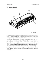
When the main motor turns on, the development roller [A] and two agitators
[B] and [C] start turning.
There are permanent magnets in the development roller which attract the
developer particles (which are about 50
µ
m in diameter) to the roller. The
turning sleeve of the development roller carries the developer past the doctor
blade [D] which trims the developer to the desired thickness.
The development roller sleeve continues to turn, carrying the developer to the
drum [E]. When the developer brush contacts the drum surface, the
negatively charged areas of the drum surface attract and hold the positively
charged toner. In this way, the latent image is developed.
The development roller is given a suitable negative bias for preventing toner
from being attracted to the non-image areas on the drum which may have a
residual negative charge. The bias also controls image density.
[D]
[B]
[E]
[A]
[C]
A219D514.wmf
DEVELOPMENT
20 December 1996
2-18
Summary of Contents for FT 4015
Page 2: ...SECTION 1 OVERALL MACHINE INFORMATION...
Page 14: ...SECTION 2 DETAILED DESCRIPTIONS...
Page 71: ...SECTION 3 INSTALLATION...
Page 90: ...SECTION 4 SERVICE TABLES...
Page 118: ...SECTION 5 PREVENTIVE MAINTENANCE...
Page 126: ...SECTION 6 REPLACEMENT AND ADJUSTMENT...
Page 190: ...SECTION 7 TROUBLESHOOTING...
Page 222: ...SECTION 8 OPTIONS...
Page 223: ...SECTION 9 APPENDIX TIMING CHART...
Page 225: ...COPIER A219 ELECTRICAL COMPONENT LAYOUT 4 2 3 1 5 6 A219S500 wmf...
Page 226: ...10 15 14 13 12 11 9 8 7 18 17 16 A219S501 wmf...
Page 227: ...24 40 23 28 27 26 25 19 20 21 22 29 39 31 32 33 34 35 36 38 37 30 A219S502 wmf...


