background image

16 April ’88

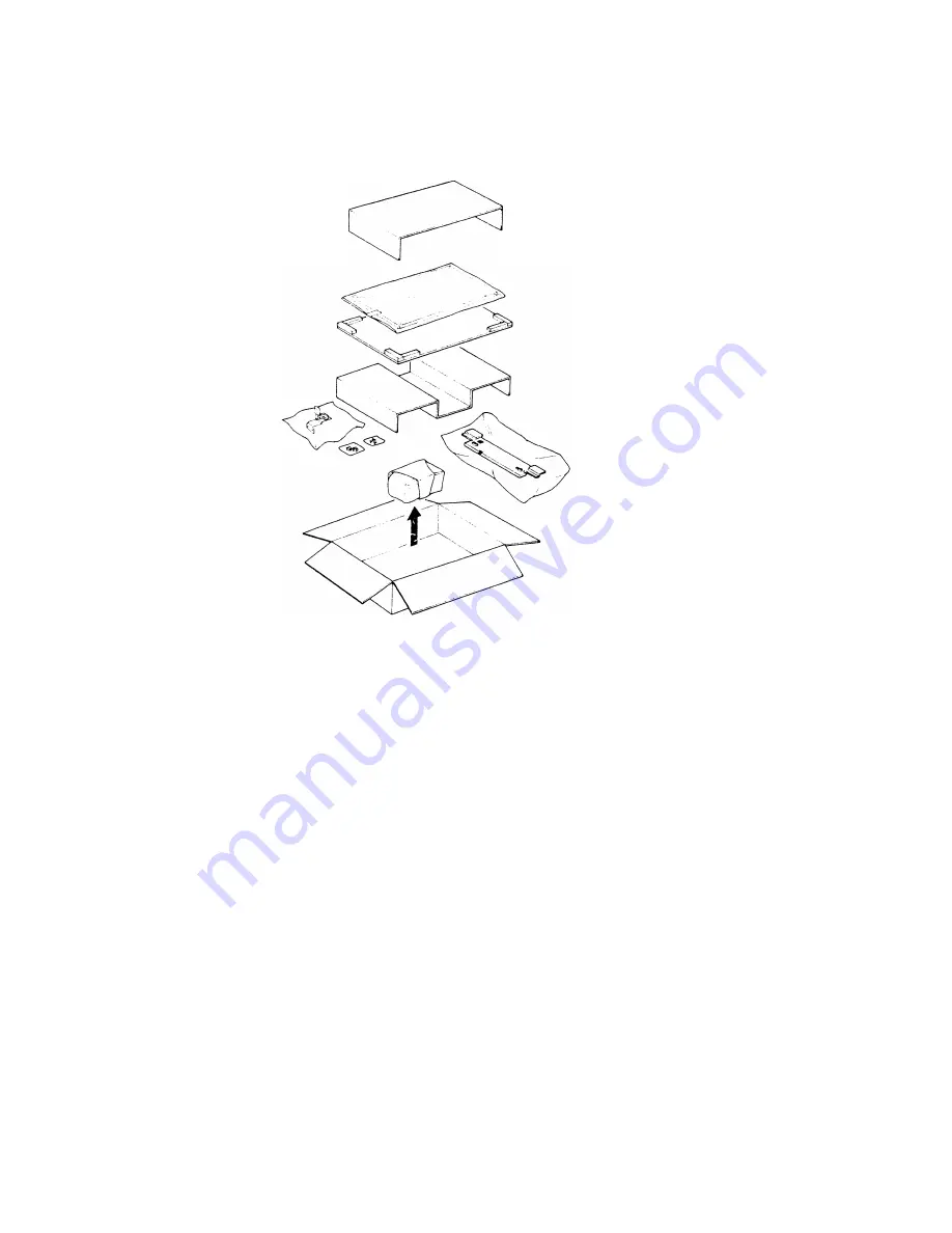
2. Installation Set for RE 11

The installation set is required when using the editor as a pressure plate.

Open the box and check the parts according to following list:

1

2 .
3 .

4,

5.
6
7,
8,

Pressure Sheet

1

Left Hinge

1

Right Hinge

1

Pan Head Screw (M4 

x 12)

12

Harness Clamp

2

Hinge Bracket (FT5560, - 115V only)

1

Mounting Stud (FT5560. - 115V only)

2

Pan Head Screw with Washer (M3 x 6)

2

(FT5560, - 115V only) ‘ ‘

NOTE:  When installing the editor on this copier, the optional erase lamp

(Editing Interface Adapter Type A) is required..

10-2

Summary of Contents for FT4430

Page 1: ...RICOH FT4430 S E R V I C E M A N U A L RICOH COMPANY LTD...

Page 2: ...SECTION 1 OVERALL MACHINE INFORMATION...

Page 3: ...Table of Contents SPECIFICATIONS OPERATION PANEL SECTION A SECTION B...

Page 4: ...lb to 34 lb Manual feed 52 to 157 g m 2 14 lb to 42 lb Reproduction Ratios See the following table v A4 Version Letter Version 1 1 41 1 1 55 Enlargement 1 1 22 1 1 29 1 1 15 1 1 21 Full Size 1 1 11 G...

Page 5: ...oximately 100 seconds 23 C Copy Number Input Numeral keys 1 to 999 count up or count down Special Functions Margin adjustment Auto size magnification mode 2 single copies mode Auto paper select and au...

Page 6: ...EDs Development System Magnetic brush roller Toner Density Control Automatic direct density sensing Development Bias Automatic voltage change The control board System monitors the selected image densi...

Page 7: ...Power Consumption Warm up 1 0 kW Stand by 0 08 kW Copying 0 42 kW A4 sideways Maximum 1 22 kW Dimensions Copier only 734 x 654 x 390 mm W x D x H 28 9 x 25 8 x 15 4 inches Full System 1363 x 654 x 46...

Page 8: ...Zoom Keys 3 Auto Reduce Enlarge Indicator 11 Size Magnification Key 4 Auto Paper Select Indicator 12 Margin Adjustment Key 5 2 Single Copies Indicator 13 2 Single Copies Key 6 Left Margin Adjustment...

Page 9: ...14 15 16 17 18 32 33 34 35 36 Auto Image Density Key Manual Image Density Key Manual Image Density Indicator Color Toner Indicator Misfeed Location Display Select Cassette Key Paper Size Indicator Ful...

Page 10: ...16 April 88 LT LDG Version 1 Number Keys 2 Recall Enter Key 3 Interrupt Indicator 4 Interrupt Key A4 A3 Version 5 Clear Modes Key 6 Start Key 7 Clear Stop Key...

Page 11: ......

Page 12: ......

Page 13: ...the fusing unit After that copies are delivered to the receiving tray 1 Paper Feed A friction pad and feed roller mechanism separates one sheet of paper from the paper stack and feeds it to the regist...

Page 14: ...um onto the 4 Paper Separation The separation corona breaks the electrostatic attraction between the paper and the drum The suction of the vacuum fan pulls the paper onto the transport belt The transp...

Page 15: ...irst Feed Roller First Cassette Second Feed Roller Pick up Roller LCT Registration Roller Pre Transfer Lamp PTL lmaqe Main Corona Unit Density Sensor Board Erase Lamp Unit 20 Transfer Separation Coron...

Page 16: ...r Drive Gear Sprockets S1 S2 S3 S4 S5 S6 Main Motor Sprocket Fusing Drive Sprocket Feed Drive Sprocket Cleaning Drive Sprocket Toner Collection Bottle Drive Sprocket Development Drive Sprocket Wire Pu...

Page 17: ...16 April 88 ELECTRICAL COMPONENT LAYOUT 1 14...

Page 18: ...uum Fan Motor M3 22 Toner Overflow Sensor S14 23 Fusing Lamp L4 24 Oil End Sensor S15 25 Paper Exit Sensor S11 26 Exhaust Blower Motor M4 27 Lamp Regulator PCB PCB1 28 Second Scanner Home Position Sen...

Page 19: ...bIowers 100Vac Positions the lens dc stepper Provides suction so that paper is held firmly on the transport belt 100 Vat Removes heat from around the fusing unit 100 Vat Positions the second scanner...

Page 20: ...ition S13 S14 Scanner Home Position Sensor Informs the CPU when the scanner is 31 at the home position Toner Overflow Sensor Detects when the used toner bottle is 22 full S15 Oil End Sensor Detects lo...

Page 21: ...Provides heat to the fusing unit Provides dc voltage for the transfer and provides ac and dc voltage for separation coronas Provides high voltage power for the charge corona and the development roller...

Page 22: ...ply unit receives ac 26 16 and 10 volts via fuses from the main transformer These voltages are rectified and regulated to 24 15 and 12 and 5 volts respectively and distributed to the sorter ADF and th...

Page 23: ...m mable 1 0 devices The main board has a RAM 2 kilobytes for the service program function A battery backs up the power to this RAM This CPU con trols the fusing lamp via the heater control board the e...

Page 24: ...and 17 segment lines Transistors drive all the scan lines at 12 volts to reduce effects from noise The multiplexing circuit lights all displays and monitors all keys of the operation panel The door sw...

Page 25: ...SECTION 2 DETAILED SECTION DESCRIPTIONS...

Page 26: ...Positioning 2 18 STEPPER MOTOR CONTROL 2 19 AUTOMATIC IMAGE DENSITY SENSING 2 20 EXPOSURE LAMP CONTROL 2 21 Service Call Conditi ons 2 22 DEVELOPMENT 2 23 overview 2 23 DRIVE MECHANISM 2 24 SEALS AND...

Page 27: ...l Detect Supply Mode 2 41 Z Fixed Supply Mode 2 41 TONER END DETECTION 2 42 COLORTONERDENSITY DETECTIONANDCOLOR TONER SUPPLY 2 42 l Color Toner Density Control 2 42 Z Color Toner End Detection 2 43 3...

Page 28: ...y with variations in the surface temperature of the drum Under cool conditions the drum may be excessively charged this will result in background or excessive image density To prevent this the CPU mon...

Page 29: ...is necessary after installing a new drum In addition it should be done at the following times 1 When image density is reduced due to over exposure of the drum 2 After cleaning the drum 3 When the drum...

Page 30: ...arge power pack P2 applies a high positive voltage The selenium coating receives a uniform positive charge 750 t 50 volts as it rotates past corona unit B The main motor fan C provides a smooth flow o...

Page 31: ...interfere with charging and cause low density bands on copies The wire cleaner B allows the operator to correct this problem by simply pulling out and pushing in the corona unit Each corona wire is he...

Page 32: ...o the power pack at CN1 1 This power supply is used for the high voltage coronas The charge corona turns on 0 42 second after the Start key is pressed A LOW signal from the main board at CN206 A22 ene...

Page 33: ...the full width of the drum B The erase lamp has three functions lead edge erase side erase and trail edge erase Trail edge erase begins after the trailing edge of the copy paper therefore the trailin...

Page 34: ...cycles the center block of erase lamps turns off long enough for the sensor pattern to be developed SIDE ERASE Based on the paper size and on the reproduction ratio the LEDs turn on in pairs one on e...

Page 35: ...peration The tables below show which erase lamps turn off size and reproduction ratio selected Note that A3 side edge erase occurs because the charge corona end block covers stop the edges of the drum...

Page 36: ...of the latent image has passed Therefore a trail edge erase margin cannot be observed on the copy Trail edge erase ON timing is the same as charge corona OFF timing During enlargement or reduction the...

Page 37: ...opier uses 34 LEDs in the erase lamp unit Shift register drivers control the LEDs Initially the RESET signal LOW active turns off all the shift registers Then the main board sends erase lamp data to t...

Page 38: ...e data in the shift registers is shifted right one position at the start of each clock cycle so it takes 34 CLOCK pulses to set the shift registers for all the LEDs After all data bits have been sent...

Page 39: ...cycle This model has eight standard reproduction ratios four reduction ratios three enlargement ratios and full size In addition it has a zoom function The user can change the reproduction ratio in o...

Page 40: ...ond scanner pulley F The pulley moves the second scanner at half the velocity of the first scanner This is to maintain the focal distance between the original and the lens during scanning This relatio...

Page 41: ...ond scanner pulley F The pulley moves the second scanner at half the velocity of the first scanner This is to maintain the focal distance between the original and the lens during scanning This relatio...

Page 42: ...drum speed by monitoring the pulses from the pulse generator Based on this input the optics CPU determines the proper speed for the scanner drive motor The optics CPU sends the speed data to the timer...

Page 43: ...lens A position in accordance with the selected reproduction ratio to provide the proper optical distance between the lens and the drum surface The lens drive motor drives the entire lens unit through...

Page 44: ...drum speed by monitoring the pulses from the pulse generator Based on this input the optics CPU determines the proper speed for the scanner drive motor The optics CPU sends the speed data to the timer...

Page 45: ...ens home position is registered each time the lens starts from or passes through the lens home position sensor As the lens moves from the enlargement side to the reduction side it registers the home p...

Page 46: ...ovides the second scanner with drive as well as correcting the second scanner position When the second scanner drive pulley B turns to change the scanner position WP1 and WP2 do not turn So the wire c...

Page 47: ...2nd scanner drive pulley using SP Mode 44 the home position may be detected when the signal goes from HIGH to LOW by calculating the adjusted magnification data When moving away from the home positio...

Page 48: ...ve M5 are stepper motors The stators of these stepper motors have four coils labeled A B A and B above and the rotors are permanent magnets Pulse signals energize the four coils as shown in the above...

Page 49: ...ing edge of the original and is 8 millimeters wide and 30 millimeters long The fiber optic cable conducts the light to a sensor photodiode on the lamp regulator The sensor circuit converts the light i...

Page 50: ...signals at CN204 6 7 and 8 The main CPU sends the lamp trigger signal 0 13 seconds after the registration clutch turns off The main CPU constantly monitors CN204 5 to check whether the lamp is on or o...

Page 51: ...me position signal to the main board The main board waits 20 seconds for this signal Self Diagnostic Codes 28 and 29 Lens Home Position Check Code 28 is displayed if the lens home position sensor stay...

Page 52: ...the latent image is developed Positive bias is applied to the development roller to prevent toner from being attracted to non image areas on the drum that may have residual positive charge The bias a...

Page 53: ...tact the drum ends out of the image area they prevent toner from scattering out of the sides Since the internal permanent magnets are shorter than the development roller sleeve the toner tends to scat...

Page 54: ...split into two parts by the doctor blade A The part that stays on the development roller B forms the magnetic brush and develops the latent image on the drum The part that is trimmed off by the doctor...

Page 55: ...to the exposure lamp causes an increase in light intensity which also results in lighter copies The method of control is different depending on whether manually selected or the automatic ID system is...

Page 56: ...image density keys At the start of the copy cycle the original sensing mechanism measures the background density of the original image It does this by measuring the strength of the light reflected fr...

Page 57: ...use the light from the exposure lamp fatigues the drum slightly and it takes a few copies for the selenium to restabilize The amount that the sensitivity drops depends on the drum s temperature and th...

Page 58: ...ature changes in the drum cavity The temperature compensation is effective from 5 degrees to 50 degrees Celsius As shown by the knee in the above chart the temperature compensation factor depends on t...

Page 59: ...es prior to which it is affected by drum cavity temperature and drum rest time The CPU applies the ID sensor bias to the development roller about 1 12 seconds after the Start key is pressed Just after...

Page 60: ...he toner the toner end detection system uses a mechanical detection system instead of an ID sensor detection system 2 Bias Control Due to the differences in the characteristics of black and color tone...

Page 61: ...5 Color Detection Color Toner Sensors Blue Green Red S A S B Toner OFF OFF Black ON OFF Blue OFF ON Green ON ON Red See the section on color toner density Three actuators each having a between the dif...

Page 62: ...ic Code 31 Drum Thermistor Open Code 31 is displayed if the drum thermistor circuit becomes open Self Diagnostic Code 32 PTL ID Sensor Boaard Ope n Code 32 is displayed if the PTL ID sensor board circ...

Page 63: ...at During the check cycles the sensor pattern is exposed prior to exposure of the original After the sensor pattern is developed its reflectivity is checked by the image density sensor which is a hoto...

Page 64: ...B is added When the image density is too low the CPU activates the toner supply solenoid to add a selected amount of toner over the next 10 copy cycles To maintain the image density precisely and pre...

Page 65: ...d to turn on the LED of the sensor VR201 adjusts the light intensity of the sensor LED Therefore the photosensor Vsg can be correctly calibrated Toner density control can be selected with SP Mode 30 I...

Page 66: ...d starts turning the toner supply drive gear The toner supply drive gear turns the toner supply roller gear D Toner catches in the grooves on the toner supply roller E Then as the grooves turn past th...

Page 67: ...ner cartridge prevents toner from blocking The toner supply roller gear engages the toner agitator gear A through an idle gear B Therefore the toner agitator gear turns whenever the toner supply clutc...

Page 68: ...de 34 and 31 Toner supply starts 0 52 second after the scanner motor reverses Toner is supplied at this time to prevent toner scattering on the copies The actual amount of toner added is determined by...

Page 69: ...the threshold level for toner color development installation procedure is determined by calculating the average of Vsp developer supply inhibition when the completed This level is and Vsg while using...

Page 70: ...oner Therefore even when the toner end lever drops to the lowest position on the cam releasing the toner end arm the toner end arm does not move and the toner end sensor F is not activated When there...

Page 71: ...of toner supply condition the Service Call indicator is not displayed and the machine can be operated SERVICE CALL CONDITION Service Call Indicator Blinks no code ID Sensor Abnormal The Service Call i...

Page 72: ...ng the paper separation process It also makes image transfer and paper separation easier IMAGE TRANSFER The registration rollers B feed the copy paper through the transfer entrance guides to the trans...

Page 73: ...auses it to separate from the drum E The separation corona has a small dc bias but its affect is negligible A dc bias is unnecessary because the separation corona is wide and diffuse The positive char...

Page 74: ...utputs a LOW signal to activate the pre transfer lamp The pre transfer lamp like the erase lamp is an array of LEDs However the CPU does not control the individual elements of the pre transfer lamp as...

Page 75: ...the power pack for the transfer and separation coronas The power pack has a dc to dc converter and a dc to ac inverter The dc to de converter changes 24 volts to 5 6 kilovolts for the transfer corona...

Page 76: ...the pawl shaft D rotates clockwise and the pick off pawls E touch the drum The pawl springs F hold the pick off pawls on the shaft and prevent them from touching the drum too strongly When the leadin...

Page 77: ...ne way bearing causes the cam rider to turn together with the pick off pawl shaft As the cam rider turns it and the pawl shaft are forced to move laterally by a cam However when the pawl shaft rotates...

Page 78: ...k off solenoid at CN206 BI 2 The CPU supplies a LOW signal at CN206 BI 1 1 69 seconds after the Start key is pressed This LOW signal energizes the pick off solenoid The CPU waits 0 99 second before tu...

Page 79: ...rom the drum surface to reduce the cleaning load placed on the blade Next the cleaning blade removes the remaining toner The falling toner catches in the fibers of the cleaning brush and is carried in...

Page 80: ...h gear B is fitted into the cleaning drive sprocket C A pin on the inside of the sprocket drives an allen screw D on the shaft of the gear turning the gear The brush gear drives the coil gear E direct...

Page 81: ...center a single pressure spring is used Side to side movement is applied to the cleaning blade to prevent uneven wear and ensure efficient cleaning The blade scraper H is mounted in contact with the b...

Page 82: ...which the pin catches so the cam wheel turns 1 6 of a revolution for each full turn of the cam drive gear The cam part of the cam wheel pushes the cam lever F out as it turns The pin on the other end...

Page 83: ...equency of the circuit stays low and the transistor stays off When toner presses against the tuning fork the resistance of the piezoelectric elements that are in contact with the tuning fork changes a...

Page 84: ...en minutes after the main motor turns off this signal becomes HIGH again turning off the solenoid This releases the cleaning blade from the drum When the cleaning blade is released the edge of the bla...

Page 85: ...copy cycle light from the quenching lamp A neutralizes any charge remaining on the drum B The LED array lamp used for quenching is similar to the pre transfer lamp PTL C however the light intensity o...

Page 86: ...he maximum paper capacity to 1 250 sheets Paper can also be fed using the manual feed table E which utilizes the feed mechanism of the first feed station All two feed stations use the feed roller and...

Page 87: ...t forward The feed roller stops turning when the trailing edge of the first sheet leaves the feed roller The leading edge of the next sheet is then held ready for feeding between the friction pad and...

Page 88: ...and force the release levers down The release levers rotate the cassette arm shaft B moving the cassette arm down and out of the way When the cassette is fully seated the release guides allow the rele...

Page 89: ...bottom plate The paper end actuator B which is on the same shaft as the paper end feeler pivots into the detector photointerrupter The paper end sensor C then sends a HIGH signal to the CPU informing...

Page 90: ...ray paper size The paper size switches A are actuated by a plate on the front of the cassette Each paper size has its own unique combination of notches in the actuator plate B The CPU reads which micr...

Page 91: ...88 PAPER FEED DRIVE The main drive chain A turns the paper feed drive sprockets The upper drive sprocket B turns the first magnetic clutch C and the second feed magnetic clutch D through the idle gear...

Page 92: ...is opened and the copy paper in the first cassette is forced down the top sheet of paper still remains between the paper feed roller and the friction pad D The spring plate installed on the manual fe...

Page 93: ...16 April 88 FEED AND REGISTRATION TIMING The following table shows the timing of the rollers used with the various feed stations Main Drive M 2 66...

Page 94: ...paper feed clutch and the LCT clutch turn off 0 09 second after the registration sensor turns on T4 If the 1st paper feed station is selected the 1st paper feed clutch turns off 0 12 second after the...

Page 95: ...the paper firmly against the belt so there is enough friction between the paper and the belt for smooth transportation The transport belt is directly gear driven no clutch so it turns constantly when...

Page 96: ...ntrol circuit monitors the hot roller surface temperature through a thermistor D The oil supply pad E applies silicone oil to the hot roller The oil blade F then spreads the oil evenly across the hot...

Page 97: ...hot roller and the pressure roller drives the pressure roller The release gear spring D allows the release gear to move in and out This prevents the gears from being damaged if they should not engage...

Page 98: ...oil cam E turns The felt wick soaks up oil and supplies it to the top of the oil supply pad F The oil supply pad then applies the oil to the hot roller as it turns The oil blade spreads and levels th...

Page 99: ...oil A covers the sensor B light C from the LED D is only refracted slightly at the boundary between the casing and the oil The phototransistor E stays off However the index of refraction of air is muc...

Page 100: ...between the paper and the roller and then direct the paper to the fusing exit rollers The lower fusing exit guide prevents the copy paper from wrapping around the pressure roller Although the lower f...

Page 101: ...using thick paper the entrance guide should be set in the lower position because thick paper does not bend so easily and is therefore less prone to creasing Also the lower setting allows more direct...

Page 102: ...the ready temperature within 8 minutes after the power is turned on Self diagnostic Code 55 Overheat The main CPU checks the conductivity of the thermistor Code 55 is displayed if the resistance of t...

Page 103: ...SECTION 3 INSTALLATION...

Page 104: ...n 2 62 PAPER SIZE DETECTION 2 63 PAPER FEED DRIVE 2 64 MANUAL FEED 2 65 FEED AND REGISTRATION TIMING 2 66 l Registration 2 67 PAPER TRANSPORT 2 68 IMAGE FUSING AND PAPER EXIT 2 69 OVERVIEW 2 69 FUSING...

Page 105: ...installation place is air conditioned or heated place the machine a Where it will not be subjected to sudden temperature changes b Where it will not be directly exposed to cool air from an air conditi...

Page 106: ...Right to left Within 5 mm 0 2 of level Place the machine on a table and screw the leveling foots A up or down to level the machine Use a leveling gauge if necessary MINIMUM SPACE REQUIREMENT 1 Front...

Page 107: ...0Hz More than 8A 240V 50Hz More than 8A 3 Permissible extension cord At least 300V 30A capacity and less than 5 meters 16 4 ft long 4 Do not set anything on the power cord NOTE Be sure to ground the m...

Page 108: ...i Arabia Philippines Asia Taiwan 5 Cassette Small America Europe Saudi Arabia Philippines Taiwan Asia 6 7 8 9 10 11 12 13 Receiving tray Original holder Operating Instructions 1 15V English only 220V...

Page 109: ...e D between the registration rollers and cut the cable tie E securing the toner collection bottle 3 Remove the scanner lock plate cover F 1 screw 4 Remove the scanner lock plate G 1 screw NOTE Save th...

Page 110: ...roper operation of the silicon oil supply system Reassemble the fusing unit and return it to its original position Raise the development lock lever F and pull out the development unit G Place the unit...

Page 111: ...ogether with the wire cleaner G 1 screw Remove the drum stay H 1 knob and 1 screw NOTE 20 Pull NOTE The drum stay knob 1 is reverse threaded out the drum protective sleeve J Save the drum protective s...

Page 112: ...on the copier 23 Install one toner cartridge B NOTE Confirm that the toner cartridge gear is properly engaged by attempting to rotate the cartridge counterclockwise When the toner cartridge gear is pr...

Page 113: ...y for drum conditioning After the machine stops turn off the main switch Turn off DIP switch 1 1 and reinstall the DIP switch cover Adhere the Operating Instructions cards A over the DIP switch cover...

Page 114: ...TION 1 Accessory Check Check the quantity and condition of the accessories in the box according to the following list 1 Actuator Red 1 pc 2 Actuator Blue 1 pc 3 Actuator Green 1 pc 4 Screw M3 x 4 1 pc...

Page 115: ...per is replaced 1 Install the colour actuator A on the colour development unit 1 screw NOTE Each actuator has a coloured sticker Install the appropriate actuator 2 Stick the appropriate decal B on the...

Page 116: ...ove the DIP switch cover C 1 screw and turn on DIP SW No 1 Plug in the machine and turn on the main switch Confirm that the colour toner indicator is displayed on the operation panel Press the Enter R...

Page 117: ...Remove the shorting plug E from the 4p key counter connector Insert the key counter harness through the access hole and connect the 4p connector of the key counter holder F to the harness Hold the fix...

Page 118: ...A 1 screw and the right inner cover B 3 screws 3 Remove the cap C from the right inner 4 Push the accessory counter D into the cover using wire cutters space provided until it locks 5 Connect the 2p c...

Page 119: ...paper size position 1 screw NOTE Paper size positions are shown on the inside of the cassette 4 5 6 7 Reinstall the bottom plate confirming the positioning pins have clicked into place Reinstall the s...

Page 120: ...ril 88 MODIFYING MAIN TRANSFORMER VOLTAGE 220V TO 240V A 1 Remove the rear cover 2 screws 2 Disconnect the 220V connector A White 1 P 3 Connect the 240V connector B Red 1 P 4 Reinstall the rear cover...

Page 121: ...ation be sure to prepare it for transportation as follows 1 Insert the drum protective sleeve A 2 Re install the development unit 3 Re install the drum stay and charge corona unit 4 Secure the followi...

Page 122: ...ers 3 Remove the scanner lock plate cover B and install the scanner lock plate C NOTE Confirm that the scanner is at the home position 4 Secure the following items with tape D F T S corona release Iev...

Page 123: ...SECTION 4 SERVICE TABLES...

Page 124: ...IER 3 17 I Short Haul Transportation 3 17 2 Long Haul Transportation By Vehicle 3 18 PO TABLE 4 1 SERVICE TABLES 4 4 TEST POINTS 1 Main Board 2 DF Main Board VARIABLE RESISTERS 1 Main Board i 2 Lamp R...

Page 125: ...MODE OPERATION 4 7 l Data Change Mode 4 7 2 Data Check Mode 4 7 SERVICE PROGRAM MODETABLE 4 8 SERVICE REMARKS 4 14 l Handling the Drum 4 14 2 Charge Corona 4 14 3 optics 0 4 15 4 Development 4 16 5 To...

Page 126: ...R Water Refer to the NOTE 2 8 Paper feed guide c c c c plate 9 Registration sensor c c c c Blower brush 10 Cassette bottom c c c c Alcohol or water plate pad 11 Paper feed sensor C c c c Blower brush...

Page 127: ...Stripper pawls c c c c Replace If necessary 34 Oil supply pad R R R R Prime with silicone oil 35 Oil blade c R c R Prime with silicone oil 36 Fusing entrance c c c c Suitable solvent and exit guides 3...

Page 128: ...1 Toner supply spring clutch Use Mobil Temp 78 2 Main Drive Chain Use Spindle Oil 3 Fusing Unit Lubricate the drive gear at every 120k using Mobil Temp 78 4 Busings Lubricate the busings at every 120...

Page 129: ...16 April 88 SERVICE TABLES TEST POINTS 1 Main Board Number Function TP206 TP207 2 DF Main Board Number Function NOTE 1 To perform scanner free run short TP101 and TP207 4 4...

Page 130: ...LE RESISTERS 1 Main Board Number Function VR201 Adjust the image density sensor voltage 2 Lamp Regulator Number Function VRI Light adjustment VR2 ADS input adjustment VR3 Factory Use 3 DF Main Board N...

Page 131: ...e run Jam detection disable Sorter instructions Beeper sound disable Copy counter count up down ON down OFF up Manual image density mode priority ON manual mode OFF ADS mode SP Mode 2 DF Main Board DI...

Page 132: ...ta is displayed in the copy counter If the data is correct press the Enter key Enter the desired data using numeral keys The data entered is displayed in the copy counter Press the Enter key to place...

Page 133: ...16 April 88 SERVICE PROGRAM MODE TABLE 4 8...

Page 134: ...16 April 88 4 9...

Page 135: ...16 April 88 4 10...

Page 136: ...modes which factory setting is O back to O Clear All counters and returns all modes to fac tory setting Displays the total num ber of paper jams Displays the total num ber of entrance area paper jams...

Page 137: ...n on the main switch then press the Start key 3 While pressing the enter key and the O key the toner supply clutch turns on 4 Press the Clear Stop key and turn off the main switch then turn off DIP sw...

Page 138: ...No 93 To change the limit quantity perform the following 1 Turn DIP SW1 8 on 2 Enter 93 using the numeral keys 3 Press the Enter key 4 Enter a desired number using the numeral keys 5 Press the Enter...

Page 139: ...inserting or pulling out the drum the cleaning unit should be pulled slightly out to avoid drum damage by the pick off pawls Return used drums to the distributor according to standard procedure 2 Char...

Page 140: ...bricate or clean the fol lowing Scanner Guide Rod Cleaning Scanner Guide Rod Pads Lubrication Scanner Guide Plate Lubrication CIeaning 4 Do not use any other kind of oil 5 6 7 8 9 10 Clean the exposur...

Page 141: ...sor PTL board is replaced The main board is replaced The drum has been replaced and Vsg is out of specification Problems with toner supply have occurred and ID sensor check shows Vsg to be out of spec...

Page 142: ...eir ten sion springs 4 Do not touch the fusing lamp with bare hands 5 Be sure that the fusing lamp is not in contact with the inner surface of the hot roller 6 Be sure that the oil end sensor contacts...

Page 143: ...before servicing it Before placing the large capacity tray in the cassette holders make sure that the paper position feeler is set properly Others When the main board is removed from the PCB plate do...

Page 144: ...4209507 54209550 54479078 54209516 54209502 54429103 Doctor Gap Gauge Switching Board Gap Gauge 0 1 mm Sensor Checker Grease Shinetsu Silicone G 501 Setting Powder Drum Shoe Shoe Adapter DigitaI Therm...

Page 145: ...SECTION 5 REPLACEMENT AND ADJUSTMENT...

Page 146: ...Paper Size Sensor Replacement 5 4o Feed Pressure Adjustment 5 41 Registration Clutch Adjustment 5 42 FeedRoller FrictionPadGapAdjustment lstand 2nd Feed Station 5 43 FUSING 5 44 l Fusing Unit Removal...

Page 147: ...ATIC Main Control MAIN BOARD SCHEMATIC Optics Control OPERATION PANEL BOARD SCHEMATIC PAPER FEED CONTROL BOARD SCHEMATIC DC POWER SUPPLY BOARD SCHEMATIC LAMP REGULATOR SCHEMATIC FUSING LAMP DRIVE BOAR...

Page 148: ...up slightly Slide the other edge out from under the right glass holder C Remove the ex posure glass NOTE When reinstalling the exposure glass Make sure that the left edge of the glass is flush with t...

Page 149: ...ass Removal Move the 1st scanner 2 3 to the right by pushing it at the rear Remove the front spring plate A by pressing the top of the spring and moving the plate towards the front of the machine Care...

Page 150: ...nd mirror B into the front side plate cut out 10 Insert the rear side of the mirror into the rear spring plate 11 Locate the bottom of the front spring plate C and rotate the top of the spring into po...

Page 151: ...screw and the reflector cover D 2 screws after unhooking the fiber optics cables Wrap a strip of paper around the exposure lamp E as shown Press the release lever F on the rear lamp terminal as shown...

Page 152: ...lector cover B in the direction of the arrow 2 screws NOTE Unhook the fiber optics cable from the reflector cover 6 7 8 9 10 Remove the exposure lamp leads C from the exposure lamp terminal D Remove t...

Page 153: ...and the upper cover 11 screws 3 Remove the left scale 2 short screws and the exposure glass 4 Remove the rear cover and lower the CB plate A 2 screws each 5 Remove the power relay bracket B 1 screw 6...

Page 154: ...tion the bead A of the new wire B on the groove of the 2nd scan ner drive pulley C and wrap the wire around the pulley with two and a half turns as shown 9 Hook the short end D of the wire to the stop...

Page 155: ...Pulley B 5 Lower track WP3 6 Inner track WP1 7 Track WP4 Pull the ends of the wire together and join them with the tension spring See the preceding page Rotate the scanner drive pulley and make sure t...

Page 156: ...platen cover and the mounting studs Remove the left scale the exposure glass and the upper cover Move the scanner to the home position Remove the lens cover A 2 screws Move the lens unit B to a reduc...

Page 157: ...the scanner drive wire as shown to avoid the scanner wire coming off Remove the E ring B from the 2nd scanner drive shaft and move the pulley slightly in the direction of the arrow Disconnect the 2nd...

Page 158: ...g off Loosen the scanner drive pulley 1 Allen screw B Remove the scanner drive pulley from the motor shaft Remove the motor bracket C 3 screws Remove the scanner drive motor D 4 screws and 2 connector...

Page 159: ...and move the lens unit A in the direc tion of the arrow 4 Replace the lens home position sensor B 1 screw and 1 connector NOTE Do not overtighten the screw when securing the new sensor 10 Scanner Hom...

Page 160: ...placement 1 Turn off the main switch 2 Remove the rear cover 2 screws 3 Remove the sensor bracket A 1 screw 4 Replace the 2nd scanner home position sensor B 1 screw and 1 con nector NOTE Do not overti...

Page 161: ...the rear sight hole C of the reflector cover D to form a right angle for viewing alignment as shown 6 View the lamp filament E through the sight hole in parallel with the scale The filament should be...

Page 162: ...mirror 10 View the lamp filament C through the sight hole reflected on the mirror The filament should be level with the sight hole NOTE If the filament cannot be seen easily use a pen light D to illu...

Page 163: ...ht when non square images appears on a copy 1 Turn off the main switch 2 Remove the exposure glass See Exposure Glass Removal 3 Loosen the alIen screw on the excentric can A using a allen screw key 4...

Page 164: ...paper B with the unit s inlet facing downward Turn the paddle roller knob C counterclockwise The developer will fall out onto the paper Hold the unit at an angle and dump out the developer that has co...

Page 165: ...oor 2 Remove the development unit A 3 Slide out the image density sensor PTL B 4 Clean and reinstall the ID sensor PTL NOTE When sliding in the ID sensor PTL board make sure that the board is properly...

Page 166: ...screw Drum stay 1 screw and 1 knob Cleaning unit Drum flange and drum should be covered with a shielding sleeve Toner shield glass 2 Remove the connector cover A 1 screw 3 Remove the sensor bracket B...

Page 167: ...ement B A 1 Remove the rear cover 2 screws 2 Remove the color toner sensor bracket A 1 screw 3 Replace the color toner sensors B 1 screw and 1 connector each 4 Reassemble NOTE Do not over tighten the...

Page 168: ...dc harness guide A to the toner supply clutch support bracket B Remove the toner supply clutch support bracket Remove the clutch hub C 1 E ring the spring D and the sleeve E Clean the clutch hub sprin...

Page 169: ...checking the ID sensor shows that Vsg is not within specifications METHOD A Readout from the CPU 1 Clean the following parts Image density sensor Optics Mirrorsj reflectors lens and toner shield glas...

Page 170: ...nter 99 in the copy counter 7 Press the Start key to show Vsg in then press the Enter key the magnification indicator 8 If Vsg is incorrect remove the rear cover 2 screws volts 0 Press the C S key to...

Page 171: ...main board Hook up the multimeter leads as follows Positive lead to TP206 Vsg Negative lead to TP201 Ground on the main board after selecting the 20 volt dc setting Turn on the main switch and enter 5...

Page 172: ...he development tank Loosen the doctor plate C 4 screws Clean the development roller and insert the Doctor Gap gauges D Part Number 521 59500 near both ends of the development roller between the doctor...

Page 173: ...16 April 88 CLEANING 1 Cleaning Unit Removal B E Be sure the pick off pawls are kept away from the drum when removing the cleaning unit or serious drum damage will result 5 26...

Page 174: ...the cleaning unit A See Cleaning Unit Removal 2 Remove the cleaning blade B 1 screw and 1 bushing 3 Install the new cleaning blade 9 Be careful not to touch the edge of the new blade After installing...

Page 175: ...C from the rear end of the cleaning brush shaft 2 Remove the bushing D from the front end 1 E ring 3 Take out the cleaning brush E with the brush shaft holder F 1 screw 4 Take the brush shaft holder o...

Page 176: ...t A 1 Remove the cleaning blade See Cleaning Blade Replacement 2 Remove the cleaning brush See Cleaning Brush Replacement 3 Take out the blade scraper A 2 screws 4 Clean the inside of the cleaning uni...

Page 177: ...er collection coil shaft 2 Remove the bottle joint seal B 3 Slide out the toner collection coil C from the front side of the cleaning unit Toner will fall out when the coil is slid out of the cleaning...

Page 178: ...ring 3 Remove the pawl shaft pin D from the pawl shaft E 4 Push the pawl shaft to the rear and slide off the cam holder F from the front side plate 5 Take out the whole pawl shaft assembly 6 Slide off...

Page 179: ...f the DF is installed 4 Lower the main PCB 2 screws 5 isconnect the AC harness from the T S power pack and remove it 1 screw 6 Lightly secure the cleaning solenoid A at the center of the bracket B 7 P...

Page 180: ...ide plate NOTE When installing the cam holder E and the cam rider F align X 11 129 with Y as shown in the figure Make sure that the spring end is in the small hole on the rear side plate Install the p...

Page 181: ...16 April 88 QUENCHING 1 Quenching Lamp Replacement 1 Remove the 2 Remove the A charge corona unit A 1 screw quenching lamp B from the charge corona unit 2 screws 5 34...

Page 182: ...feed table hinges A from the copier 1 snap ring B each side Be careful not to damage the manual feed sensor C 2 Slide the lower manual feed table grooves to remove the table hinge pins D down their r...

Page 183: ...oller 5 Strip the old friction pad G off and clean the surface of the friction pad holder 6 Install the new friction pad 7 Grease the friction pad holder swivel point with Mobil Temp 78 8 Reinstall th...

Page 184: ...ide out the registration sensor B 1 connector NOTE When sliding in the registration sensor board make sure that the board is properly located on the rails When reinstalling the support bracket make su...

Page 185: ...e Manual Feed Table Removal 2 Remove the rear cover 2 screws 3 Remove the right rear cover 2 screws 4 Remove the sensor cover B 1 screw 5 Remove the manual feed sensor C 1 screw 1 connector 6 Install...

Page 186: ...16 April 88 5 Paper End Sensor Replacement A 1 Remove the rear cover 2 screws 2 Remove the paper end sensors A 1 connector each 4 Be careful not to damage the paper end sensor actuator 5 39...

Page 187: ...Remove the paper size sensor A from the sensor bracket B 1 screw and 1 connector 2 Install a new sensor Position the projection of the sensor in the hole of the sensor bracket NOTE Do not overtighten...

Page 188: ...djustment 1 2 Remove the rear cover Move the pressure spring A to the desired position see the following table Setting Feed Pressure Function A 350 g To prevent multi feed B 400 g Factory setting c 45...

Page 189: ...which is to be ad justed 1 Allen screw Place the adjusting collar next to the lock collar on the clutch shaft Position a 0 1 mm gap gauge C Part number 52059101 between the two collars Push the colla...

Page 190: ...the friction pad holder B to make the gap between the feed roller and the pad 3 Measure the gap between the feed roller and the pad using a gap guage c 4 If the gap is not within the adjustment stand...

Page 191: ...er A to the right 3 Pull out the fusing unit B until it is fully extended 4 Push the fusing unit release lever to the right move the fusing unit to the left to disengage the stopper pin C and remove t...

Page 192: ...fusing unit cover A 2 screws 3 Remove the pressure plate B 2 screws 4 Remove the oil supply pad C 2 screws and 2 clamp plates D 5 Unhook the two tension springs E 6 Turn and remove the oil blade asse...

Page 193: ...s and 1 connector 5 Rotate the front lamp terminal E and remove the fusing lamp F Do not touch the fusing lamp with oily fingers because oil marks may damage the lamp 6 Swing down the fusing exit asse...

Page 194: ...each Slide the hot roller slightly to the rear and remove the hot roller as shown Tear the protective paper E from the ends of a new hot roller and install it After the new hot roller is installed re...

Page 195: ...p mechanism C with the oil tank D 2 screws and 1 connector 5 Open and remove the fusing exit assembly E 1 E ring 1 connector and 2 springs 6 Remove the oil pan F 4 screws and 4 hooks 7 Remove the fron...

Page 196: ...ement 1 Pull out the fusing unit and open the fusing exit assembly A 2 Unhook the springs B and remove the hot roller strippers C 3 Install new strippers and connect the springs NOTE It is best to rep...

Page 197: ...y pad C 2 screws and 2 clamp plates D 5 Remove any excess oil from the oil sump and remove the oil sump E 6 Unhook the thermistor spring F 7 Remove the thermistor wire from the metal wire clamp G 1 sc...

Page 198: ...lacement 2 Remove the thermofuse bracket A 1 screw 3 Remove the oil pump mechanism B with the oil tank C 2 screws and 1 connector 4 Remove the thermofuse wire from the front lamp terminal D 1 screw 5...

Page 199: ...he fusing unit knob 1 screw 4 Remove the oil pump mechanism along with the oil tank 2 screws 1 con nector 5 Move the pressure springs A to the desired position See the following table Setting Fusing P...

Page 200: ...b A to the front to raise the fusing guide plate B Move the knob to the rear to the rear to lower the fusing guide plate The movement range is 1 mm NOTE Normally the entrance guide is set in the lower...

Page 201: ...toner overflow sensor connector B Remove the toner collection bottle C Remove the development unit D PTL board E and the charge corona unit F 1 screw Lower the T S corona unit G Remove the drum stay H...

Page 202: ...ansport unit from the mounting bracket B 2 screws Slide the transport unit and vacuum fan out of the copier NOTE When reinstalling the transport unit be sure the transport gear 13 14 15 engages with t...

Page 203: ...Fan Motor Replacement 1 Remiove the transport belt See Transport Unit and Transport Belt Removal 2 Remove the transport plate A from the vacuum fan unit B 3 screws and 1 connector 3 Remove the fan mo...

Page 204: ...r etc as it will damage the corona wires When removing the endblock covers be careful not to break off the side hooks Do not use any solvents to clean the wire as it will cause uneven charge on the dr...

Page 205: ...brush and dry cloth 7 Hook the new corona wire onto the and the corona tension spring c unit casing with a 8 Hook the other end of the wire onto the front anchor post using a small screw driver When i...

Page 206: ...up the guide stopper D from underneath Then remove the guide from the corona unit Remove the front E and rear F endblock covers Unhook the tension springs G from the front anchor posts H and remove th...

Page 207: ...on corona wire through the hole in the rear endblock and hook the terminal spring onto the nearby wire junction Hook the tension spring onto the other end of the loop and then hook the spring to the f...

Page 208: ...paper separation incomplete toner transfer or image density Make sure that the main switch is turned off when you change the range on the digital multimeter If not the multimeter may be damaged Take...

Page 209: ...hes on the switching board A should be off 6 7 8 9 Install the drum shoe and adapter on the drum shaft with the lip to the rear Route the shoe lead wire out through the development unit opening Connec...

Page 210: ...e corona wire as shown Reinstall the drum stay 1 screw and 1 knob and the charge corona unit Select the dc 200 VA range of the digital multimeter B Turn on SW 8 of the switching board Turn on the main...

Page 211: ...Turn it counterclockwise to decrease the reading reading After adjusting the front side confirm the rear reading once again 9 Turn off the main switch and position the drum shoe on the center of the...

Page 212: ...transfer corona wire as shown 2 Reinstall the cleaning unit and the drum stay 1 screw and 1 knob 3 Select the dc 200 VA range of the digital multimeter B 4 Turn on SW 3 of the switching board 5 Turn o...

Page 213: ...6 7 8 9 10 Turn on SW 4 on the switching board Turn on the main switch and adjust the separation dc current by turning DDC on the power pack T S C Wait 30 seconds for the corona cur rent to stabilize...

Page 214: ...Operation Panel Removal 1 Remove the DIP switch cover A under the instructions cards 1 screw 2 Remove the front cover 3 Remove the right inner cover B 3 screws 4 Remove the operation panel C 2 screws...

Page 215: ...r Supply Unit Removal 1 Remove the power supply unit cover A 4 screws 2 Remove the harness clamps B 1 screw each 3 Remove the heat plate C 9 screws 4 Disconnect all the connectors 5 Remove the power s...

Page 216: ...inner cover 6 screws and the rear cover 2 screws Disconnect the lens drive motor connector and the 2nd drive motor con nector Remove the main charger power pack 2 screws and 3 connectors Remove the f...

Page 217: ...en the 4th level of the density control is selected 1 2 3 4 Clean the optics mirrors lens reflectors exposure glass toner shield glass Turn on the main switch and allow it to warm up Set the image den...

Page 218: ...h bracket B 1 screw Adjust VR1 on the lamp regulator board to achieve properly illuminated copies Confirm that the image density is within the standard NOTE If the test copies are made within 3 minute...

Page 219: ...ent before performing the Auto ID sen sor adjustment Remove the DIP switch cover 1 screws Turn off the main switch and turn on DIP switche Nos 1 1 and 1 8 Open the manual feed table and remove the mag...

Page 220: ...umeral keys then press the Start key 10 Adjust the Auto ID sensor by turning VR2 on the lamp regulator board NOTE Continue the adjustment procedure until the value is within specifications When adjust...

Page 221: ...the operation panel 2 Open the manual feed table and remove the magnetic catch bracket 1 screws 3 Remove the rear cover 2 screws 4 Hook up the multimeter leads as follows NOTE Hook up the positive lea...

Page 222: ...99 using the numeral keys Press the Start key after the copier warms up 7 Adjust the Auto ID sensor by turning VR2 on the lamp regulator board NOTE Adjust the Auto ID sensor after the 3rd copy cycle h...

Page 223: ...py image to reduce the copy image Viewed from the rear side wire clamp A 1 Move it to the left Method B Using SP Mode 44 which can adjust the position of 2nd scanner by turning the drive pulley cam B...

Page 224: ...t ADJUSTMENT STANDARD O 1 Place a 150 mm scale on the exposure glass aligning it with the left scale 2 Make 3 copies with the ID level at the No 7 position 3 Adjust the lead edge registration using SP...

Page 225: ...SECTION 7 DOCUMENT FEEDER...

Page 226: ...nt 7 35 Lead Edge Registration Adjustment 7 36 DFMAIN BOARD SCHEMATIC DF TIMING CHART SORTER SPECIFICATIONS MECHANICAL COMPONENT LAYOUT ELECTRICAL COMPONENT LAYOUT BASIC OPERATION I Clear Mode 2 Sort...

Page 227: ...TIONS Original Size Weight Original Feed Modes Original Capacity Original Separation Original Transportation Original Stop System Original Feed Speed Power Source Power Consumption Dimensions WXDXH We...

Page 228: ...16 April 88 MECHANICAL COMPONENT LAYOUT Feed Roller Pick up Roller Original Table Registration Rollers 7 2...

Page 229: ...4 10 DF Main PCB PCB I 1 3 Feed in Sensor S 34 11 Belt Drive Motor M 16 4 Entrance Sensor S 35 12 Pick up Solenoid Sol 7 5 Registration Sensor S 37 13 Registration Solenoid Sol 8 6 Width Sensor S 36 1...

Page 230: ...ns on the feed in motor Ml 4 The feed D and friction rollers E separate and feed an original to the registration rollers F A short time after the original reaches the registration roller the DF CPU tu...

Page 231: ...riginal s At the same time the DF CPU energizes the original stopper solenoid Sol 1 O to retract the stopper claws B In ADF mode the original stopper claws stay underneath the original feed table unti...

Page 232: ...feed system with three sets of rollers feed friction and pick up roller The feed A and friction rollers B have grooves in them which interlock with one another The rollers interlock to decrease damage...

Page 233: ...n these rollers the friction roller rotates counter clockwise a few degrees to help feed thick originals D After the friction roller has rotated a few degrees the misfeed prevention lever contacts the...

Page 234: ...er drive gear rotates the high point of the cam pushes back the wear prevention lever in the A direction As the cam rotates to the low point a spring returns the wear prevention lever to its original...

Page 235: ...which has an eccentric cam A on each end to decrease the overlap of the feed and friction rollers This is to prevent the original from being smeared by the friction roller B The overlap is 0 9 mm whe...

Page 236: ...s counting the pulses from Ml 6 when the leading edge of the original activates the registration sensor S 37 When the pulse count reaches 1 962 pulses about 940 ins the original is at the proper posit...

Page 237: ...motors The feed out motor M 1 5 drives both the lower exit roller A and the upper exit roller B through an idle gear When the exit sensor S 38 detects the trailing edge of the original the CPU reduces...

Page 238: ...am plates B are sandwiched between the brake shoes C which are under pressure from the brake shoe springs D This causes friction between the cam plate and the brake shoes When the belt unit is lifted...

Page 239: ...nce sensor is activated the DF CPU checks to see if the registration sensor has been activated registration sensor ON check The OFF check is carried out when the belt drive motor M 16 is de energized...

Page 240: ...ness bushing 12 Test chart A4 13 Flathead screw M4 x 6 14 Ground screw 15 Toothed washer 16 Pan head screw M4 x 6 17 Pan head screw with washer M4 x 6 18 Pan head screw M5 x 12 19 Multilingual decals...

Page 241: ...ver 3 screws G ADF docking hole cap 2 pcs NOTE Save the above parts for future use 3 Install the exposure glass holders H at the left side of the exposure glass as shown 220 240 V only 4 Set the flip...

Page 242: ...sert the mounting posts B into the DF mounting brackets C Temporarily secure the mounting posts to the DF mounting brackets 4 screws M5 x 12 Remove the DF cover D 4 screws Remove the shipping foam E b...

Page 243: ...he original table 4 screws Level the DF as follows a Remove the DF grip plate F 2 screws b Place 2 sheets of A3 11 x 17 paper between the white belt guide spacers G and the exposure glass c Loosen the...

Page 244: ...ront and rear left corners Adjust the two amounts so that they are the same by using the left height adjusting bolt B on the DF mounting bracket Adjust the right rear height adjusting bolt C so that t...

Page 245: ...sure to match these colours when making these connections 17 18 19 Secure the DF ground wire F on the DF base plate 1 ground screw and toothed washer Pass the Ty wrap G through the hole of the vinyl...

Page 246: ...already installed in the machine 22 Connect the 3 DF connectors a Connect two fiber optic connectors C to the interface board as follows being careful not to damage them CN806 Brown CNI 03 CN807 Blac...

Page 247: ...nce and mark PM Platen Mode on the reverse side of it c Make a copy in DF mode using the test chart d Adjust the Df registration against the platen mode reference PM using VR10I on the DF PCB B PM DF...

Page 248: ...the lock plate C 4 Rotate the belt release bracket D counterclockwise and lower the original entrance guide E 5 Lower the DF grip bracket F and release the belt G from the belt guide spacers H 6 Slide...

Page 249: ...the DF cover 4 screws 2 collars 2 Lift up the pick up roller unit A and remove the snap ring B 3 Slide off the rear pick up roller C NOTE Be careful not to lose the pin 4 Remove the E ring D and bushi...

Page 250: ...16 April 88 c B 6 Slide off the pulley A and the pick up roller B NOTE Be sure not to lose the drive pins C of the pulley and pick up roller 7 Replace the pick up rollers and reassemble 7 24...

Page 251: ...3 Feed Roller Replacement B A c 1 Remove the DF cover 4 2 Remove the pick up control shaft A 1 snap ring B 1 pin c 3 Remove the feed in motor D 2 screws 4 Unhook the spring E of the wear prevention l...

Page 252: ...oller drive gear C 1 E ring D 1 bearing E Remove the collar F 1 Allen screw G and the bearing on the front feed roller shaft H Stand the feed roller unit 1 and slide the feed in guides as shown in the...

Page 253: ...bushing C and slide the pulley towards the front to remove the pulley pin D 12 Slide the pick up roller unit E to the front and remove the E ring 13 Slide the feed roller F to the front and remove the...

Page 254: ...lowing points 1 2 Confirm that the wear prevention lever A is to the right of the drive gear B as viewed from the rear Tighten the Allen screw of the feed roller shaft C collar D so that the clearance...

Page 255: ...rews 2 collars 2 Remove the original table cover A 4 screws 3 Remove the original table B 2 screws 4 Remove the lever spring C and the stopper plate D 2 screws 5 Remove the feed in motor E 2 screws 1...

Page 256: ...t the original entrance guide B 8 Unhook the spring C of the misfeed prevention lever D and remove the misfeed prevention lever and the bushing E 1 E ring F 9 Remove the wear prevention lever G 1 E ri...

Page 257: ...pin F When reassembling the unit make sure of the following points When replacing the collar on the friction roller shaft position the friction roller so that it is centered on the feed roller When re...

Page 258: ...the registration solenoid harness C and roller release solenoid harness D 2 red connectors Move the indicator board and the harness bracket E 1 screw away from the feed in section Remove the springs...

Page 259: ...he registration clutch assembly B 1 E ring 10 At the front remove the lever spring C and lower the original entrance guide D 11 Remove the registration drive gear E 1 E ring 1 pin F NOTE Do not lose t...

Page 260: ...cam D aligns with the 4 calibration mark NOTE This means that the overlap of the feed and friction rollers is adjusted to 0 4 mm when the friction roller is released from the feed roller If the cam ca...

Page 261: ...d the left two digits of the motor speed will be displayed in the original counter To display the second two digits of the motor speed press the Counter Reset key For example if the motor speed is 250...

Page 262: ...and mark PM Platen Mode on the reverse side of it c Make a copy using the test chart with the DF d Adjust the DF registration to match the PM reference copy using VR101 on the DF PCB B PM DF Turn VR10...

Page 263: ...SECTION 8 SORTER...

Page 264: ...8 4 3 Stack Mode 8 4 4 Example of Sort Mode Operation 8 5 BIN DRIVE MECHANISM 8 6 BINS 99 8 7 EXIT ROLLERS 8 8 ELECTRICALCONTROL 8 9 SORTER INSTALLATION 0 8 10 l Accessory Check 8 10 REPLACEMENT AND...

Page 265: ...nterface Equipment Maximum A3 11 x 17 Minimum 66 51 2 x 81 2 50 to 110 grams 14 to 28 lb 20 bins proof tray Sort Mode 30 sheets A4 81 2 x 11 10 sheets A3 11 x 17 Stack Mode 30 sheets A4 81 2 x 11 10 s...

Page 266: ...16 April 88 MECHANICAL COMPONENT LAYOUT Exit Rollers 4 Bins 2 Bin Drive Wheel 5 Roller Drive Belt 3 Proof Tray...

Page 267: ...COMPONENT LAYOUT 1 Paper Sensor S 31 2 Wheel Drive Motor M 11 3 Roller Drive Motor M 12 4 Bin Home Position Sensor S 32 5 Wheel Sensor S 33 6 Sorter Control PCB PCB 9 7 Cover Safety Switch SW 9 8 Rela...

Page 268: ...ive motor turns on to move the proof tray up When the first sheet of paper activates the paper exit sensor the roller drive motor turns on Shortly after the paper sensor turns off 345 ms later the whe...

Page 269: ...sorter will stay at this position until auto reset or until copying resumes Start Kev ON 4 5 6 The first copy is fed to the third bin After the paper detector turns off the wheel drive motor turns on...

Page 270: ...on either side of each bin are inserted into slots in the sorter side frame The pins slide up and down in these slots The bins rest on each other with the lower one resting on the lift bar C The spri...

Page 271: ...When all the bins are lowered the lift bar presses down on the actuator actuating the sensor The CPU checks the sensor whenever the power is turned on At this time if the bins are not in the home pos...

Page 272: ...and is mounted on the transfer wheel shaft Al coaxial When the copy actuates the copier s exit sensor the CPU send a signal to the sorter to turn on the roller drive motor The roller drive motor turn...

Page 273: ...lies 100 volts ac to the wheel drive motor and the SSRS SSR 101 turns the wheel drive motor to move the bins up and SSR 102 is for the down operation The copier supplies two dc power levels components...

Page 274: ...ingual Decal 220 240V only 1 Interface PCB Type E and Sorter Adapter Type E are also required to install the sorter Check the accessories according to the following list Sorter Adapter Type E box 1 Mo...

Page 275: ...of the copier 3 Remove the receiving tray B and rear cover C 2 screws 4 Remove the five plastic caps D from the left cover 5 Remove the sorter covers E 2 screws each 6 Install the sorter adapter F on...

Page 276: ...D and two knob screws E Connect the sorter ac harness F free red 2P connector Connect the sorter dc harness G CNI 02 free white 4P connector Secure the sorter ground wire H 1 screw with toothed washe...

Page 277: ...ier and the sorter adapter from the sorter 2 Remove the front and rear covers 2 screws each 3 Remove the ground wire A of the upper guide plate B 1 screw 4 Swing the guide plate up then remove it by c...

Page 278: ...the wheel drive motor and slip off the timing belt G Slide off the wheel drive shaft H and remove the exit roller 1 and O ring J Do not damage the paper sensor K when removing the exit roller 13 Repl...

Page 279: ...the copier and the sorter adapter from the sorter 2 Swing up the guide plate A 3 Remove the inner cover B 4 screw 4 Replace the paper sensor C 1 screw and 1 connector and reas semble To avoid damagin...

Page 280: ...tion at 200 g 0 44 lb pressure 200 g 0 44 lb 1 2 3 Remove the front cover Loosen the four mounting screws A of the wheel drive motor B Press the timing belt C with a tension gauge D as shown in the fi...

Page 281: ...SORTER CONTROL BOARD SCHEMATIC IOOV AC s 1 0 2 1 b 4 16 April 88 A024...

Page 282: ...SECTION 9 LARGE CAPACITY TRAT...

Page 283: ...9 5 3 Paper Size Detection 9 6 ELECTRICALOPERATION 9 7 l Down Operation 9 7 Z Up Operation 0 9 7 LARGE CAPACITY TRAY INSTALLATION 9 8 l Accessory Check 9 8 REPLACEMENTAND ADJUSTMENT 9 12 l Tray Wire R...

Page 284: ...A4 length or width B5 length or width 81 2 x 14 length 81 2 x 11 length or width 50gto ll0g 141b to 281b 1 000 sheets may vary slightly depending on paper weight Maximum 12 seconds 50 Hz 10 seconds 6...

Page 285: ...16 April 88 MECHANICAL COMPONENT LAYOUT 1 Drive Wire 2 Drive Gears 3 Drive Pulley 4 Tray Wire 5 Lift Rods 9 2...

Page 286: ...8 LCT transformer T 2 LCT PCB PCB 12 Ac fuse F 2 220 V Circuit breaker CB 2 115 V LCT motor M 17 LCT safety switch SW 11 Tray down sensor S 39 Positioning switch SW 1 2 Paper size sensor S 40 LCT ope...

Page 287: ...irectly to the tray drive shaft B via a worm gear and worm wheel The tray wires C have braces on them these braces hold the ends of the two lift rods which support the tray bottom plate The braces on...

Page 288: ...initialize feed paper from the LCT The paper end sensor C and the upper limit sensor D are incorporated in the LCT not the copier The paper end sensor is used to detect paper end and the upper Iimit...

Page 289: ...the inside rim of the dial and the positioning switch 1 deactuates When the positioning switch opens the scan signal is applied to the LCT paper size sensor The paper size sensor then reads the patter...

Page 290: ...the flip flop to change back to its original state which turns off SSR1 and resets the timer circuit The LED in the Down key stays continuously on 2 Up Operation Opening and closing the upper or side...

Page 291: ...6 7 8 9 104 11 12 following list Installation procedure 115V English only 220V five languages New Equipment Condition Report Envelope NECR 1 15V only Pick up roller assembly Feed Gear Mounting Bracket...

Page 292: ...le Remove the rear cover 2 screws Remove the rear right side cover A 2 screws Remove the paper feed PCB B 2 studs Remove the cassette arm lever spring C Remove the cassette arm assembly D 1 screw Pres...

Page 293: ...sette holder on the 2nd feed sta tion NOTE Make sure that the rib of the tray side plate fits into the groove of the 17 18 19 cassette holder Open the side and top covers and secure the tray to the 2n...

Page 294: ...C on the feed roller shaft Install the gear D on the feed roller shaft Reinstall the feed roller E 1 snap ring F Make sure that the paper position feeler G is positioned as shown Reinstall all covers...

Page 295: ...rd harness 1 screw Rear Wire 1 Remove the LCT from the copier 2 Remove the following parts 1 Rear cover 5 screws 2 Transformer assembly A with tray main board B 1 screw 8 connectors and 1 nylon clamp...

Page 296: ...he drive pulley C as shown one and a half turns Run the wire over WP1 WP2 WP3 and WP4 in turn while also placing the lift rod s ends in the braces Insert the bead D red into the other slot of the driv...

Page 297: ...Remove the sensor bracket A 2 screws There is no need to discon nect the sensor connector 4 Remove the two post tops B 3 screws each 5 Remove the tray bottom plate C 4 screws taking care not to damag...

Page 298: ...nt inner cover B 1 short and 1 long screw 9 Replace the tray down sensor C 1 screw and 1 connector 10 Rotate the paper size dial to a smaller size such as A4R and remove the positioning switch bracket...

Page 299: ...switch replace ment procedure 2 Remove the front guide post A 1 screw and 1 hook 3 Remove the paper size sensor bracket B 1 screw 4 Replace the paper size sensor C 1 screw and 1 connector NOTE When i...

Page 300: ...ecuring the pinion bracket A Loosen the screw securing the guide post lock plate B Move the pinion bracket while holding the pinion so that the pinion does not turn The front and rear guide posts must...

Page 301: ...SECTION 10 EDITOR BOARD...

Page 302: ...CONTENTS...

Page 303: ...Installation Procedure 115V English only 220 240V Five languages 2 New Equipment Condition Report 3 NECR Envelope 115V only 4 Operation Instructions 115V English only 220 240V Five languages 5 stylus...

Page 304: ...to following list 1 2 3 4 5 6 7 8 Pressure Sheet 1 Left Hinge 1 Right Hinge 1 Pan Head Screw M4 x 12 12 Harness Clamp 2 Hinge Bracket FT5560 115V only 1 Mounting Stud FT5560 115V only 2 Pan Head Screw...

Page 305: ...mage key or Centering key with the stylus 1 Place the cover plate A over the Shift Image key and the Centering key 2 Remove the bottom plate B of the editor 11 screws 3 Remove the shorting connector C...

Page 306: ...ite core B as shown in the figure NOTE Step 1 is only required in the European machines 2 Plug the stylus jack into the editor board as shown 3 Remove the screw securing the bottom plate as shown and...

Page 307: ...cover is installed on the machine the connector should be connected through the cutout in the docking hole cap as shown on page 10 8 7 8 9 10 Clamp the editor harness D to the main board bracket with...

Page 308: ...il 88 5 Installation Procedure on the Machine 1 Remove the platen cover A from the machine 2 Remove the platen cover hinge bracket B from the platen cover 3 Remove the feet C from the editor 4 screws...

Page 309: ...p 5 is only required for European machines 6 Plug a stylus jack into the editor as shown 7 Remove the screw securing the bottom plate and secure the lock plate D to it NOTE Step 7 is only required in...

Page 310: ...ws NOTE Use the screws which secure the platen cover to the copier 11 Remove the rear cover D and remove the right docking hole cover E 12 Remove the cap F from the right docking cover using a small s...

Page 311: ...install the rear cover Install the editor on the copier Put the pressure sheet C on the exposure glass so as to align the image area indicators Remove the seal Close the edifor to complete the install...

Page 312: ...SECTION 11 TROUBLESHOOTING...

Page 313: ...sity Appears ln Bands 11 8 ABNORMAL IMAGE DENSITY 11 9 l image Densltyls Too High Or Too Low 11 9 VERTICAL BLACK LINES ORBANDS 11 9 l Wavy Lines 11 9 2 Dotted LinesorBands 11 10 3 Line or Band Appears...

Page 314: ...ON 11 21 LENS HOME POSITION SENSOR NOT OFF 11 21 2ND SCANNER HOME POSITION SENSORNOTON 11 22 2NDSCANNERHOME POSITION SENSOR NOTOFF 11 22 SCANNER MOTOR TOO FAST 11 23 SCANNER MOTOR TOO SLOW 11 23 DRUM...

Page 315: ...e image density too light Y N 1 Correct Clean the ends of the development roller Replace the developer and the side seals the light copy condition Refer to Light Copy section 2 Small Spots Possible Ca...

Page 316: ...conditioning HAT IMAGE Possible Causes Defective quenching lamp Charge corona wire miscounted Incorrect corona current Old developer Action Does the quenching lamp turn on Y N I I Does CN203 8 drop fr...

Page 317: ...and reset the wire s UNFUSED COPY 1 Image Can be Easily Rubbed Off Possible Causes Thermistor malfunction Very low early morning temperatures Copy paper has a very rough surface Action Does the probl...

Page 318: ...of jitter change when making reduced copies Y N H I Check the main drive belt Replace the tensioner spring if it is stretched Clean the scanner guide rods then apply a small amount of Launa oil to the...

Page 319: ...ce the damp paper with fresh paper VERTICAL WHITE LINES OR BANDS 1 Lines 80 mm Apart Possible Causes Damaged pick off pawis Pick off mechanism malfunction Action Does the pick off pawI mechanism work...

Page 320: ...any parts which scratch the hot roller If the hot roller strippers are badly stained with toner check and adjust the fusing temperature Then replace the hot roller Is the drum scratched Y N I Follow t...

Page 321: ...darker area follow the image Y N I IClean the charge corona wires when making reduced copies Are the charge corona wires incorrectly positioned in the wire cleaner and end block Y N I Is the charge co...

Page 322: ...quenching lamp Dirty corona wire incorrect corona current Action Does the darker area move with the image when making reduced copies Y N I P Clean the charge corona wire across the drum Are any of the...

Page 323: ...density is too light use SP Mode 60 to supply toner VERTICAL BLACK LINES OR BANDS 1 Wavy Lines Possible Causes Dust between the cleaning blade and drum Edge of the cleaning blade deformed Insufficien...

Page 324: ...ls swing properly Y N I I Correct or replace the Is the gap between the drum Y N pick off pawls and replace the drum I If the pick off pawl mechanism does not work properly correct or replace any defe...

Page 325: ...the same lines on it Y N I If the hot roller surface is scratched clean correct or replace any parts scratching the surface Note If the hot roller strippers are badly toner stained check and adjust th...

Page 326: ...il replace it if Clean the cleaning unit Check the toner collection damaged Check RA3 Make sure the cooling fan operates properly BLACK SPOTS AT THE LEADING EDGE Possible Cause Separation corona wire...

Page 327: ...th A3 11 x 17 paper Does the dirty background ap pear in the erased areas Y N I F Clean the drum thermistor and bias thermistor surfaces I If the problem was not resolved adjust the lamp regulator out...

Page 328: ...the cleaning blade Check that the edge of the blade scraper is straight and that its movement is smooth If not correct or replace any defective parts If the problem still exists one of the following s...

Page 329: ...P Clean the charge corona unit and remove any foreign substances that might cause a leak F If the problem still exists replace the charge power pack Reset the charge corona wire or unit Does the dens...

Page 330: ...ace the main board Check for electrical continuity between the bias terminal and the development sleeve Correct any poor contact or faulty wiring If that isn t effective replace the bias power pack Do...

Page 331: ...hick paper is being used Action Is the gap between the friction pad and feed roller 1 6 0 3 mm Y N I I Adjust the friction pad feed roller gap Do the feed problems occur mostly with the cassette tray...

Page 332: ...cooling fan work Y N I I Check the cooling fan circuit Replace the cooling fan if it is defective Turn the main switch off and on Does SC 11 remain off Y N I Replace the exposure lamp if the exposure...

Page 333: ...sor failure Action Move the scanner away from the home position Turn the main switch off and on Does the scanner move to the home position Y N I I Check repair the scanner drive mechanism Manually act...

Page 334: ...turn to home position within 20 seconds after scanner start Optics control circuit failure Scanner home position sensor failure Action Does the scanner return to the home position within 20 seconds af...

Page 335: ...nsor Does CNI 01 B3 stay LOW Replace it if defective If the above does not work replace the main board 29 LENS HOME POSITION SENSOR NOT OFF Possible Causes Lens does not move properly Lens home positi...

Page 336: ...r Replace it if defective Does CN101 B4 stay LOW If the above does not work replace the main board 2B 2ND SCANNER HOME POSITION SENSOR NOT OFF Possible Causes Second scanner drive doesn t work properl...

Page 337: ...SLOW Possible Causes Scanner motor control circuit failure Action Replace the main board 31 DRUM THERMISTOR Possible Causes Drum thermistor circuit open Drum thermistor circuit short Action Is the in...

Page 338: ...nit Adjust Vsg using VR201 on the main board Vsg should be 4 0 0 2 volts If the problem still exists check the input at CN203 5 Is it less than 1 0 volt Y N I IReplace the PTL unit Replace the main bo...

Page 339: ...n 8 minutes after the power relay turns on Is the fusing m Y N I Is the Y lamp mamem moKen thermistor circuit open N I Check the thermistor Make sure it is mounted properly and in good Replace the Rep...

Page 340: ...N I I Replace the thermistor Replace the fusing lamp 61 PULSE GENERATOR ABNORMAL Possible Causes Main drive malfunction Pulse generator sensor failure Action SC 61 lights if the main board does not re...

Page 341: ...upply if it is not correct Replace the main board if Vaa is all right Replace the operation panel Does CNI 03 5 pulse from 5 V to O V at the start of the copy cycle Y N I I Replace the total counter R...

Page 342: ...tion If Vsg becomes less than 2 5 volts the SC indicator lights but no number is displayed The copier shifts to fixed toner supply mode Clean the ID sensor If the problem still exist replace the PTC u...

Page 343: ...dition The CPU never detects toner end condition Lights Add Toner indicator even when enough toner is present Lights Manual Feed indicator even when the manual feed table is closed Never lights Manual...

Page 344: ...RICOH FT4430 A024 P A R T S C A T A L O G First Edition April 1988 RICOH COMPANY LTD...

Page 345: ...und Drum A024 18 Cleaning Unit A024 20 Development Unit A024 22 Drive Section A024 24 Paper Transport A024 26 16 17 18 19 20 21 22 23 24 25 26 27 28 Paper Exit A024 30 Electrical Section 1 A024 32 Ele...

Page 346: ...1 EXTERIOR A024 April 30 88 2...

Page 347: ...Panel Ass y A3 A4 1 16 A024 1255 Left Inner Cover LT LDG 1 16 A024 1250 Left Inner Cover A3 A4 1 17 A024 1362 Cap Left Cover 1 18 A024 1371 Front Cover Grip 2 19 5443 2713 Wave Washer 1 20 A024 1373...

Page 348: ...Index No 101 102 103 104 105 106 107 108 109 110 Part No 0314 0080W 0434 0060W 0434 0080W 0720 0050E 0802 5085 0802 5086 0802 5094 0964 4008W 0965 3006W 0344 0060W Q ty Per Assembly 3...

Page 349: ...2 REGISTRATION A024 April 30 88...

Page 350: ...751 5215 2670 5215 2671 5215 2612 AX21 0011 5205 2866 5215 2672 5205 2697 Paper Guide Harness PTL Collar 8mm Spring Registration Roller Knob Registration Roller Upper Regist Roller Lower Regist Roller...

Page 351: ...3 PLATEN COVER AND CASSETTE A024 April 30 88...

Page 352: ...27 5205 2963 Actuator B 5 R 1 27 5205 2964 Actuator A4 1 27 5205 2965 Actuator B5 1 27 5205 2966 Actuator A 5 1 27 5205 2967 Actuator A 5 R 1 Index Part No D e s c r i p t i o n Q ty Per No Assembly 2...

Page 353: ...4 PAPER FEED A024 April 30 88 8...

Page 354: ...r End Feeler 2 34 A024 2579 Lower Paper Feed Stay 1 35 A024 2575 Lower Front Arm 1 Index Part No Description Q ty Per No Assembly 36 A024 2580 Shaft Lower Paper Feed 1 37 A008 2656 Lower Lift Arm 1 38...

Page 355: ...an Head Screw M4x8 105 0314 0120W Philips Pan Head Screw M4x12 106 0323 0080W Philips Sunken Head Screw M3x8 107 0434 0060W Tapping Screw M4x6 108 0434 0080W Tapping Screw M4x8 109 0720 0025E Retainin...

Page 356: ...34 A024 2579 Lower Paper Feed Stay 1 35 A024 2575 Lower Front Arm 1 April 30 88 r Index Part No Description Q ty Per No Assembly 36 A024 2580 Shaft Lower Paper Feed 1 37 A008 2656 Lower Lift Arm 1 38...

Page 357: ...5 OPERATION PANEL A024 10 April 30 88...

Page 358: ...AG01 1087 Key Top Reduce 1 24 A009 1557 Sort Stack Cover Plate L T L K 1 24 A009 1481 Sort Stack Cover Plate A3 A4 1 25 A009 1476 Sort Stack Cover 1 26 AG01 1070 Key Top 1 1 27 AG01 1092 Key Top Zoom...

Page 359: ...6 FRAME A024 April 30 88 12...

Page 360: ...Left Grip Bottom Plate 1 15 A024 1063 Front Right Grip Bottom Plate 1 16 5419 1057 Rubber Foot 4 17 A024 1453 Operation Panel Bracket Left 1 18 A024 5826 Support Plate 1 19 A024 1151 Exit Tray Bracke...

Page 361: ...7 OPTICS 1 A024 April 30 88...

Page 362: ...ley Sub Harness Optics 141 Lamp Regulator 115V Lamp Regulator 220V Development Unit Cover Lamp Regulator Harness Stepper Motor DC 7 5W Lens Motor Seal 141 Stepper Motor DC 7 5W 141 Spring Plate 4th Mi...

Page 363: ...8 OPTICS 2 A024 April 30 88 16 1...

Page 364: ...T 1 29 AA16 1031 Cushion Exposure Glass 6 30 A024 1650 2nd Scanner Shaft 1 31 5211 1733 Bushing 2nd Scanner 1 32 5442 1748 Cleaner Guide Rod 1 33 5209 1735 Pulley 1 34 5211 1734 Idle Pulley 1 35 5209...

Page 365: ...9 AROUND DRUM A024 April 30 88 18...

Page 366: ...S Corona Guide 1 29 AD02 2042 Rear End Block Cover T S Corona 1 30 5205 3821 Terminal Spring 2 31 AD02 2040 Rear End Block T S Corona 1 32 5215 2119 T S Corona Guide Plate 1 33 5442 3585 Bushing 1 34...

Page 367: ...g Screw M4x6 107 0434 0080W Tapping Screw M4x8 108 0720 0030E Retaining Ring M3 109 0725 0120E Retaining Ring C M12 110 0951 3006W Philips Screw With Flat Washer M3x6 111 0951 4008W Philips Screw With...

Page 368: ...10 35 CLEANING UNIT A024 April 30 88 20...

Page 369: ...AB01 7036 Gear 33T 1 22 A009 3598 Side Seal 2 23 5205 3968 Set Screw Separator Shaft 1 24 5418 2116 Spacer Guard 1 25 5205 3966 Set Screw 2 26 A009 3599 Brush Seal 2 27 A024 3558 Rear Side Plate Clea...

Page 370: ...11 DEVELOPMENT UNIT A024 April 30 88 22...

Page 371: ...ler 1 28 5215 3101 Gear 44T 1 29 5215 3089 Developer Knob 1 30 5215 3120 Toner Supply Guide 1 31 5931 3330 Toner End Lever 1 32 5215 3056 Seal Development 2 33 A008 3078 Lower Casing 1 34 AA15 l194 Se...

Page 372: ...Philips Pan Head Screw M4x20 105 0720 0025E Retaining Ring M2 5 106 0720 0050E Retaining Ring N5 107 0720 0070E Retaining Ring M7 108 0725 0140E Retaining Ring C Pl14 109 0725 0220E Retaining Ring C...

Page 373: ...I April 30 88 24...

Page 374: ...24 1160 Cam Follower 1 30 5053 0447 Bushing M6 1 31 5442 1110 Sprocket 20T 2 32 5211 1099 Sprocket Gear 30T 1 33 5215 3951 Chain Guide 2 34 5215 3865 Sprocket 20T 1 35 5215 2597 Idle Gear 30T 2 Index...

Page 375: ...13 PAPER TRANSPORT A024 April 30 88 26...

Page 376: ...21 AB01 3214 Gear 20T 1 22 5215 3677 Roller 2 23 5215 3675 Roller Holder 2 24 5215 3928 Duct 1 25 A024 3877 Plate 1 26 5215 3878 Sheet 1 27 5053 0223 Bushing 8mm 1 28 5215 5426 Vacuum Fan Motor 14 lN...

Page 377: ...14 FUSING UNIT A024 April 30 88 28...

Page 378: ...1l 3008 Front Lamp Terminal 1 30 AG05 0011 Knob Fusing 1 31 5209 4408 Gear 1 6 T 1 32 5209 4149 Fusing Unit Shaft 1 Index No 33 34 35 36 37 38 39 40 41 42 43 44 45 46 47 48 49 50 51 52 53 54 55 56 57...

Page 379: ...34 0060W Tapping Screw M4x6 105 0434 0080W Tapping Screw M4x8 106 0434 Ol00W Tapping Screw M4x1O 107 0720 0030E Retaining Ring M3 108 0720 0050E Retaining Ring MS 109 0720 0060E Retaining Ring M6 110...

Page 380: ...15 PAPER EXIT A024 April 30 88 10 6 30...

Page 381: ...1 5442 4492 A009 4314 A009 4315 A009 4316 5205 4305 5215 9002 AF04 0001 4009 4317 A009 4304 AA08 0014 5053 0447 5875 2067 5442 4495 5442 4494 Gea r 19Z Index Part No Description Q ty Per No Assembly 1...

Page 382: ...16 ELECTRICAL SECTION 1 A024 April 30 88 32...

Page 383: ...1 A009 5270 Harness Paper Feed 2 12 A024 1685 Harness Cover 1 13 A024 1145 Power Supply Unit Cover 1 14 A024 5803 Left Angle Control Board 1 15 A009 5125 Power Relay Board 1 16 A024 5275 Relay Harness...

Page 384: ...17 ELECTRICAL SECTION 2 A024 April 30 88...

Page 385: ...Philips Pan Head Screw M4x8 103 0434 0080W Tapping Screw M4x8 104 0801 1185 Philips Truss Head Screw M4x8 105 0964 4008W Tapping Screw With Flat Washer M4x8 106 1105 0197 Wire Saddle 107 1106 0395 Loc...

Page 386: ...INDEX NO SYMBOL NO...

Page 387: ......

Page 388: ...114 1103 0750 Pin Huosing 2P 115 1103 1894 Connector 20P 116 1104 0271 LSI Socket 28P 117 1104 0339 IC C5W64 11 118 1400 0369 IC 2SA1213 119 1401 0296 Transistor 2SA1162Y 120 1401 0298 Transistor 2SC...

Page 389: ...l 8W 5 1610 0039 Resistor 150Q l 8Wk5 1610 0041 Resistor 180Q l 8W 5 1610 0044 Resistor 2LQ 1 8W 1610 0048 Resistor 390Q l 8W i5 1610 0049 Resistor 470Q l 8W 5 1610 0053 Resistor IKQ l 8W 5 1610 0055...

Page 390: ...19 FUSING LAMP DRIVE BOARD A024 April 30 88 38...

Page 391: ...102 1405 0130 Rectifier 1G4B42 115V 102 1405 0152 Rectifier IJ4B42 220v 103 1102 2117 Connector 2P 104 1102 0997 Connector 6P 105 1405 0127 Photothyristor TLP541G 115V 105 1405 0151 Photothyristor TLP...

Page 392: ...20 POWER RELAY BOARD A024 CONNECTOR SYMBOL INDEX NO NO CN1 101 CN2 102 ch3 f 103 DIODE SYMBOL INDEX 1 NO NO D1 D2 104 D3 RESISTOR April 30 88 RESISTOR ARRAY SYMBOL INDEX NO No RA3 106 I 40...

Page 393: ...ssembly 1 A009 5125 Power Relay Board 1 Index No Part No 101 1102 2227 102 1102 1172 103 1103 1591 104 1402 0467 105 1600 1292 106 1208 1064 I Description Spring Header 4P EI Connector 4 P Connector 2...

Page 394: ...5 107 CN226 105 CN227 107 CN230 102 CN231 106 DIODE SYMBOL INDEX NO NO D220 109 D221 109 D222 109 D223 109 D224 109 D225 109 D226 109 D227 109 D228 109 D229 109 April 30 88 FUSE RESISTOR ARRAY SYMBOL...

Page 395: ...ty Per No Assembly A024 5250 Paper Feed Control Board 1 Index No 101 102 103 104 105 106 107 108 109 110 111 112 Part No 1102 2117 1102 2118 1102 2806 1103 0781 1103 1725 1103 1726 1103 1729 1107 032...

Page 396: ...22 AC MAIN HARNES A024 April 30 88 113 118 103 44...

Page 397: ...5 1100 1172 Fastening Receptacle 106 1100 1241 Socket Mate N Lock 107 1100 1247 Terminal 108 1102 0782 Connector 4P 109 1102 0983 Connector 2P 110 1102 0987 Connector 6P 111 1102 1005 Connector 1P 112...

Page 398: ...23 DC MAIN HARNESS A024...

Page 399: ...ription Q ty Per No Assembly 121 1102 1509 Connector 4 P 122 1102 1510 Connector 6P 123 1102 1511 Connector 9P 124 1102 1513 Connector 15P 125 1102 1621 Connector 4P 126 1102 1677 Connector 3P 127 110...

Page 400: ...24 FUSING UNIT HARNESS A024 2 101 104 April 30 88...

Page 401: ...embly 1 A009 6031 Fusing Unit Harness 1 2 A009 5431 Thermofuse Ass y 1 Index Part No Description Q ty Per No Assembly 101 1102 1620 Connector 3P 102 1102 1910 Connector 2P 103 1102 2099 Connector 12P...

Page 402: ...25 COUNTER HARNESS A024 50...

Page 403: ...Short Connector 1 51 Index Part No Description Q ty Per No Assembly 101 1103 1345 Connector 14P 102 1102 1509 Connector 4P 103 1100 1240 Socket Mate N Lock 104 1102 0185 Connector 4P 105 1100 0844 Soc...

Page 404: ...Short Connector 1 51 Index Part No Description Q ty Per No Assembly 101 1103 1345 Connector 14P 102 1102 1509 Connector 4P 103 1100 1240 Socket Mate N Lock 104 1102 0185 Connector 4P 105 1100 0844 Soc...

Page 405: ...26 HARNESS PAPER FEED A024 1 J 52...

Page 406: ...on Q ty Per No Assembly 1 A009 5270 Harness Paper Feed 1 1ndex Part No D e s c r i p t i o n Q ty Per No Assembly 101 1102 1915 Connector 7P 102 1102 1911 Connector 3P 103 1103 1897 Connector 3P 104 1...

Page 407: ...27 SPECIAL TOOL A024 April 30 88...

Page 408: ...5203 9501 Grease 501 1 7 5442 9101 Setting Powder 1 8 5442 9106 Drum Shoe 1 9 5447 9104 Shoe Adaptor 1 10 5420 9504 Thermo Meter HLC60 E 1 11 5420 9505 Probe HLC60 E 1 12 5420 9507 Digital Multimeter...

Page 409: ...28 DECAL AND DOCUMENT April 30 88...

Page 410: ...o BI 12 15 8 1 6 WARNING HIGH TEMP 9...

Page 411: ...ed LT LDG 1 10 AA00 2013 Deca 1 Manual Feed A3 A4 1 11 AA00 1039 Decal B1 1 12 5420 4667 Decal Thermofuse 169 C 1 13 5211 5809 Decal Terminal 115V 1 13 5447 4980 Deca 1 Terminal 220V 1 14 AA00 2010 De...

Page 412: ...DF 39 A419...

Page 413: ...1 Document Feeder l A419 2 2 Document Feeder II A419 4 3 Document Feeder III A419 6 4 DF Main Board A419 8 5 DF Harness A419 10 Parts Index 13...

Page 414: ...1 DOCUMENT FEEDER I A419 April 30 88 2...

Page 415: ...DF Main Board 1 21 A419 2645 Key Top D 1 22 A419 5621 Display Board 1 April 30 88 I n d e x Part No Description Q ty Per No Assembly 23 5918 2390 Display Board Bracket 2 24 5918 2725 Mylar Feed in 1 2...

Page 416: ...0160W Philips Pan Head Screw M3x16 X MB1 102 0314 0060W Philips Pan Head Screw M4x6 103 1204 0770 Reed Microswitch 104 0316 0100G Philips Pan Head Screw M6x1O MB1 105 0344 0600D Philips Truss Head Sc...

Page 417: ...2 DOCUMENT FEEDER II A419 April 30 88 4...

Page 418: ...ick up Roller Bracket 1 33 5918 2375 Pick up Control Shaft 1 34 5918 5501 Stopper Solenoid 1 35 5918 5515 Pick up Solenoid 1 Index No 36 37 38 39 40 41 42 43 44 45 45 46 47 48 49 50 51 52 53 54 55 56...

Page 419: ...s Pan Head Screw M 3 x 4 104 0805 3145 Ball Bearing 6x12x4mm 105 0965 4006W Tapping Screw M4x6 106 0965 3010W Tapping Screw With Flat Washer M3x1O 107 0574 0040E Hexagon Headless Set Screw M4x4 108 05...

Page 420: ...3 DOCUMENT FEEDER Ill A419 April 30 88 6...

Page 421: ...0 5918 3523 Exit Motor Bracket 1 31 5918 3516 Exit Drive Motor DC1 69W 1 32 5936 5501 Transport Drive Motor DC 21W 1 33 5918 2270 Pulley 1ST 1 34 5918 2321 Timing Belt Tightener 1 Index Part No D e s...

Page 422: ...3x6 107 0632 0100E Pin M2x1O 108 0965 3010W Tapping Screw With Flat Washer M3xI0 109 0951 4006W Philips Screw With Flat Washer M4x6 110 0720 0025E Retaining Ring P12 5 111 0720 0040E Retaining Ring M4...

Page 423: ...119 C120 C121 POTENTIOMETER NDEX NO 149 146 150 150 147 149 147 149 149 147 lNOEX NO 103 102 104 105 106 NDEX No 149 148 151 148 151 148 150 151 147 151 INDEX NO 147 149 147 149 149 147 149 149 146 14...

Page 424: ...00 0569 Resistor 0 2Q lW 128 1600 0576 Resistor 33Q SW 129 1601 1732 Resistor 390Q IW 130 1601 7326 Resistor Array 10KQ 131 1601 8145 Variable Resistor 5KQ 132 1601 8147 Variable Resistor 10KQ 0 5W 13...

Page 425: ...5 DF HARNESS A419 April 30 88 10...

Page 426: ...cket Mate N Lock 107 1100 1327 Contact 108 1100 1328 Contact 109 1100 1348 Pin Contact 110 1102 1089 Connector 3P 111 1102 1244 Connector 15P 112 1102 1289 Connector 6P 113 1102 1350 Connector 5239 2P...

Page 427: ...CS 2070 A414...

Page 428: ...1 Mini Sorter A414 2 2 Bin Motor Board A414 4 3 Sorter Harness A414 6 Parts lndex 9...

Page 429: ...1 MINI SORTER A414 April 30 88 2...

Page 430: ...1 28 6803 2111 Lower Guide Plate 1 29 A414 1131 Base Plate 1 30 6803 4411 Cover Bracket 1 31 6803 4216 Pulley 1 32 6803 4316 O Ring 1 April 30 88 Index Part No D e s c r i p t i o n Q ty Per No Assemb...

Page 431: ...ilips Pan Head Screw M4x12 111 0313 0120W Philips Pan Head Screw M3x12 112 1606 0755 Capacitor 10PF 220V 115V 112 1606 1380 Capacitor I0AF 220 240V 113 0314 0080W Philips Pan Head Screw M4x8 114 0965...

Page 432: ...2 BIN MOTOR BOARD A414 CONNECTOR DIODE SSR r SYMBOL INDEX SYMBOL INDEX SYMBOL INDEX No NO NO NO NO NO CN1O1 101 D101 106 SSR101 105 CN102 102 D102 106 SSR102 105 CN103 104 CN104 103 1 1 J...

Page 433: ...in Mate N Lock 105 1100 1239 Pin Mate N Lock 106 1100 1249 Receptacle Terminal 107 1100 1264 Terminal 108 1100 1327 Contact 109 1100 1328 Contact 110 1102 0512 Connector 3P 111 1102 0983 Connector 2P...

Page 434: ...RT 15 A912...

Page 435: ...1 LCT I A912 2 2 LCT II A912 4 3 LCT III A912 6 4 LCT Board A912 8 5 LCT Harness A912 10 Parts Index 13...

Page 436: ...1 LCT I A912 April 30 88...

Page 437: ...rease Size 1 12 A912 2595 Decal Decrease Size 1 13 A912 2546 Paper End Plate 1 14 AA14 8023 Feeler Shaft 1 15 A912 2547 Paper Position Feeler 1 16 AA06 6011 Spring Paper Position Feeler 1 17 A912 2540...

Page 438: ...2 LCT II A912 4...

Page 439: ...D e s c r i p t i o n Q ty Per No Assembly 30 5205 5250 L E D Sensor Type S 1 31 5897 4103 Bracket Shaft 1 32 5897 1498 Harness Cover 2 1 33 5925 2203 Front Bracket 1 34 5897 4477 Leaf Spring 1 35 59...

Page 440: ...3 LCT Ill A912 April 30 88...

Page 441: ...ssembly 6803 5500 Bin Motor Board 1 Index Part No Description Q ty Per No Assembly 101 1102 0995 Connector 2P 102 1102 1194 Pin Connector 3P 103 1103 1695 Connector 15P 104 1103 1748 Connector 12P 105...

Page 442: ...3 SORTER HARNESS A414 April 30 88 120 115...

Page 443: ...211 AC Harness 115V 1 18 5925 5215 AC Harness 220 240V 1 19 5925 2266 Power Cord Bracket 1 20 5925 2247 Drive Shaft 1 21 5925 2251 Front Wire Tightener 1 22 5925 2211 Front Side Plate 1 23 5897 1472 W...

Page 444: ...109 0965 4010W Tapping Screw With Flat Washer M4x1O 110 0720 0030E Retaining Ring M3 111 0720 0040E Retaining Ring M4 112 0807 7021 Spacer 113 0574 0050E Hexagon Headless Set Screw M4x5 114 1005 0383...

Page 445: ...0 110 110 110 CN1OO CN101 CN102 CN103 CN104 CN105 105 104 102 103 101 106 116 119 118 117 117 118 119 119 119 120 120 119 119 119 119 117 119 117 R1OO R101 R102 R103 R104 R105 R106 R107 R108 R109 122...

Page 446: ...2 1407 0622 IC HD74LS1OP 113 1407 0981 IC TD62503P 114 1408 0124 IC LM555CN 115 1408 0412 IC 7705CP 116 1604 0909 Capacitor l F 35V 117 1604 1363 Capacitor IO F 25V 118 1604 1366 Capacitor 47PF 25V 11...

Page 447: ...5 LCT HARNESS A912 April 30 88 110 122 10...

Page 448: ...9 1100 1247 Terminal 110 1100 1249 Receptacle Terminal 111 1100 1327 Contact 112 1100 1328 Contact 113 1102 0796 Insulating Sleeve 3 Omm z z o v 114 1102 1404 Receptacle Housing 115 1102 1408 Connecto...

Page 449: ...RE 11 A906...

Page 450: ......

Page 451: ...1 RE 11 A906 April 30 88 2 5 2 4 _ _ _ 2...

Page 452: ...1 A906 5100 Indicator Board 1 12 A908 1451 Platen Cover 1 13 A906 1350 Bottom Cover 1 14 A906 1351 Rubber Foot 4 15 A906 1301 Harness Supporter 1 16 A906 5101 Main Board LT 1 16 A906 5109 Main Board A...

Page 453: ...PARTS INDEX...

Page 454: ...dicator Board 3 11 A906 5101 Main Board LT 3 16 A906 5102 Multiplexer Board 3 19 A906 5103 Harness l15V 3 18 A906 5104 Core Ring 3 17 A906 5105 s t y l u s 3 8 A906 5106 Stylus Europe 3 8 A906 5108 Ha...

Page 455: ...Tapping Screw M3x1O 3 107 0413 0102W Tapping Screw M3xlo 3 102 0413 0162B Tapping Screw M3x16 3 103 0414 0122W Tapping Screw M4x12 3 110 0705 0030B Toothed Washer M3 3 105 0710 0030B Hexagon Nut M3 3...

Page 456: ...INTERFACE BOARD TYPE E A426...

Page 457: ...1 interface Board A426 2 Parts Index 5...

Page 458: ...09 C109 109 Cll0 109 SYMBOL INDEX NO NO CN101 102 CN102 101 CN103 1 CN104 2 SYMBOL INDEX NO No IC101 106 IC102 103 IC103 105 IC104 107 IC105 104 SYMBOL INDEX NO 8 No R101 114 R102 112 R103 113 R104 11...

Page 459: ...0040B Hexagon Nut M4 2 1 5918 5711 Fiber Output Connector 1 2 5918 5712 Fiber Input Connector 1 3 I n d e x No 101 102 103 104 105 106 107 108 109 110 111 112 113 114 Part No I D e s c r i p t i o n 1...

Page 460: ...PARTS INDEX...

Page 461: ...1895 Connector 30P 3 102 1106 0395 Locking Support 3 1407 1886 IC MSM82C51FP 3 103 1407 2052 IC SN74LS74ANS 3 104 1407 2055 IC TD62304F 3 105 1407 2057 IC M5M82C55AFP 5 3 106 1408 0395 IC AN6912S 3 1...

Page 462: ...SORTER ADAPTER TYPE E A918...

Page 463: ...1 SORTER ADAPTER A918 April 30 88 2...

Page 464: ...1241 Transport Roller 1 8 6803 5410 DC Motor 2LV 2 9W 1 9 A918 1211 Lower Guide Plate 1 10 A910 6511 Deca1 Exit 1 11 5917 1216 Rubber 8x10mm 2 12 5917 1641 Original Holder 1 13 6769 1127 Lower Mountin...

Page 465: ...e main switch is turned on Check Paper Path indicator lights 1 010 pulses after pressing the Start key ON check timing Lights SC No 2b 3 seconds after the main switch is turned on Lights SC No 2A 0 3...

Reviews: