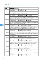
2111
[Manual Execut.] Manual Line Position Adjustment Execution
2111 001
Position Adjust.
Performs the line position adjustment.
2111 002
Pro. Position Adj.
Performs an approximate line position adjustment.
2111 003
Skew Adjust.
Performs the skew adjustment.
2111 004
ID S. Adjust.
Tests the ID sensor.
2111 005
Area.Magni.Clr.
Clears the area magnification setting.
2120
[LD Off Check]
Displays the LD off check state.
2143
[ID S. Display] ID Sensor Display
The ID sensor assembly has three sensors: Left, Center, Right
2143 001
PWM: Left
*EGB
Displays the PWM value for each sensor.
[0 to 512 / 0 / 1/step]
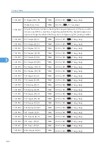
2143 002
PWM: Center
*EGB
2143 003
PWM: Right
*EGB
2143 004
Avg: Left
*EGB
Displays the average output from each sensor.
[0.00 to 5.00 / 0.00 / 0.01 volt/step]
2143 005
Avg: Center
*EGB
2143 006
Avg: Right
*EGB
2143 007
Max: Left
*EGB
Displays the maximum output from each sensor.
[0.00 to 5.00 / 0.00 / 0.01 volt/step]
2143 008
Max: Center
*EGB
2143 009
Max: Right
*EGB
2143 010
Min: Left
*EGB
Displays the minimum output from each sensor.
[0.00 to 5.00 / 0.00 / 0.01 volt/step]
2143 011
Min: Center
*EGB
2143 012
Min: Right
*EGB
2143 013
Max2: Left
*EGB
Displays the maximum 2 output from each sensor.
[0.00 to 5.00 / 0.00 / 0.01 volt/step]
2143 014
Max2: Center
*EGB
2143 015
Max2: Right
*EGB
2143 016
Min2: Left
*EGB
Displays the maximum 2 output from each sensor.
Service Mode Table
171
5
Summary of Contents for G-P3
Page 1: ...Model G P3 Machine Code G190 SERVICE MANUAL January 2008 Subject to change...
Page 11: ...10...
Page 77: ...11 Harness guide C x 2 12 Drive unit D x 6 x 16 3 Replacement and Adjustment 76 3...
Page 91: ...3 Replacement and Adjustment 90 3...
Page 137: ...LEDs No LEDs are used for this model except for the Network Interface 4 Troubleshooting 136 4...
Page 337: ...5 Service Tables 336 5...
Page 411: ...MEMO 410...
Page 412: ...MEMO 411...
Page 413: ...MEMO 412...


