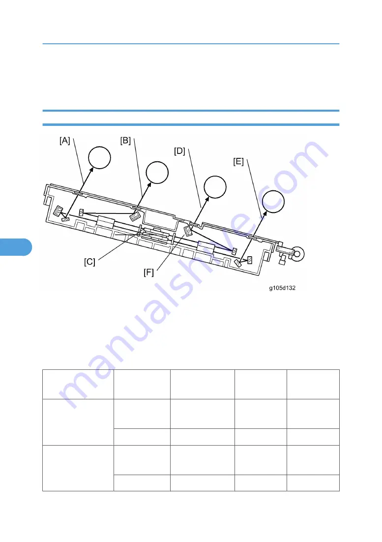
Laser exposure for yellow and cyan starts from the right side of the drum, but for magenta and black it starts
from the left side of the drum. This is because the units for yellow and cyan are on the other side of the
polygon mirror from the units for magenta and black.
Optical Path
The laser beams for cyan [B] and magenta [D] are sent to the upper part of the polygon mirror [C]. The
laser beams for yellow [A] and black [E] are sent to the lower part of the polygon mirror. The LD mirrors
(see the previous page) reflect the laser beams for yellow and black to the lower polygon mirror.
The mirror [F] corrects the main scan line. Without this mirror, the line bends at the middle of the main scan.
The central bend of the mirror is adjusted in the factory.
The speed of the polygon mirror depends on the selected mode (see below).
Mode
Resolution (dpi)
Polygon motor
speed (rpm)
Process line
speed (mm/s)
Print speed
(ppm)
B/W
(except OHP/
Thick paper)
600 x 600
1,200 x 600
42993
182
30
1,200 x 1,200
42993
91
15
Color
(except OHP/ Thick
paper)
600 x 600
1,200 x 600
42993
182
30
1,200 x 1,200
42993
91
15
6. Detailed Function Descriptions
368
6
Summary of Contents for G-P3
Page 1: ...Model G P3 Machine Code G190 SERVICE MANUAL January 2008 Subject to change...
Page 11: ...10...
Page 77: ...11 Harness guide C x 2 12 Drive unit D x 6 x 16 3 Replacement and Adjustment 76 3...
Page 91: ...3 Replacement and Adjustment 90 3...
Page 137: ...LEDs No LEDs are used for this model except for the Network Interface 4 Troubleshooting 136 4...
Page 337: ...5 Service Tables 336 5...
Page 411: ...MEMO 410...
Page 412: ...MEMO 411...
Page 413: ...MEMO 412...


