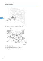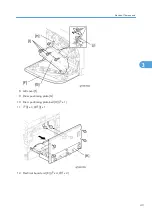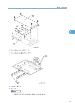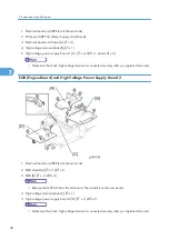
4. Replace the NVRAM on the EGB and reassemble the machine.
5. Plug in the power cord.
6. Turn on the main power switch.
7. Start the SP mode.
8. Contact your supervisor to enter the machine’s device number.
• SC542 may be displayed until the machine’s device number and destination code are
programmed properly.
9. Turn the main power switch off and on.
10. Start the SP mode.
11. Use SP5-801-002 to reset the engine settings.
12. Reset the meter charge settings (SP5-930-001).
13. Enter the SP mode changes previously made at the factory and the field.
14. Replace all maintenance kits with new ones.
NVRAM on the Controller
1. Start the SP mode.
2. Use SP5-990 to print out the SMC reports (“SP Mode Data” and “Logging Data”) if possible.
3. Use SP5-824 to upload the NVRAM data if possible.
4. Turn off the main power switch and unplug the power cord.
5. Replace the NVRAM on the controller and reassemble the machine.
6. Plug in the power cord.
7. Turn on the main power switch.
8. Start the SP mode.
9. Use SP5-825 to download the NVRAM data if possible. If it can be done, the following steps are not
required.
10. Use Memory Clear (SP5-801) to reset this data:
• SCS (SP5-801-003)
• PRT (SP5-801-008)
• NCS (SP5-801-011)
11. Do Counter Clear (SP7-810).
12. Make these contract-related settings:
• Counter Method (SP5-045)
3. Replacement and Adjustment
50
3
Summary of Contents for G-P3
Page 1: ...Model G P3 Machine Code G190 SERVICE MANUAL January 2008 Subject to change...
Page 11: ...10...
Page 77: ...11 Harness guide C x 2 12 Drive unit D x 6 x 16 3 Replacement and Adjustment 76 3...
Page 91: ...3 Replacement and Adjustment 90 3...
Page 137: ...LEDs No LEDs are used for this model except for the Network Interface 4 Troubleshooting 136 4...
Page 337: ...5 Service Tables 336 5...
Page 411: ...MEMO 410...
Page 412: ...MEMO 411...
Page 413: ...MEMO 412...


