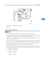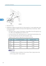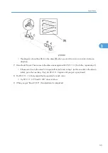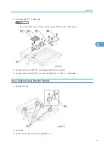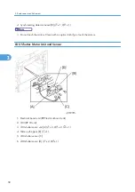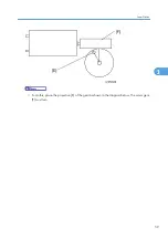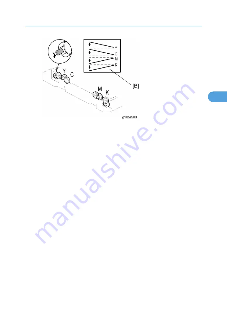
• The diagram shows the effect on line skew [B] when you turn the cam in a counter clockwise
direction.
7. Close the left cover. Then measure the skew values again with SP 2111 3. (To do this, repeat step 3.)
• If these are close to the value for magenta that you found in step 1 (within one click in the above
table), go to the next step. If not, do SP 2111 3 again until you get a good result.
8. Do SP 2111 1 to finely adjust the line position for each color.
• Try SP 2111 2 if “Result = OK” does not show.
9. When you get “Result = OK”, this adjustment is completed.
Laser Optics
55
3
Summary of Contents for G-P3
Page 1: ...Model G P3 Machine Code G190 SERVICE MANUAL January 2008 Subject to change...
Page 11: ...10...
Page 77: ...11 Harness guide C x 2 12 Drive unit D x 6 x 16 3 Replacement and Adjustment 76 3...
Page 91: ...3 Replacement and Adjustment 90 3...
Page 137: ...LEDs No LEDs are used for this model except for the Network Interface 4 Troubleshooting 136 4...
Page 337: ...5 Service Tables 336 5...
Page 411: ...MEMO 410...
Page 412: ...MEMO 411...
Page 413: ...MEMO 412...

