


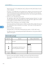


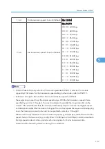


6 to 8
Extension of incoming calling signal (CI)
frequency band specified by selectors 1
through 4 on WSW14
No. 6 7 8
0 0 0 : 0 (Ignored)
0 0 1 : 4 (448 Hz)
0 1 0 : 8 (244 Hz)
0 1 1 : 12 (162 Hz)
1 0 0 : 16 (122 Hz)
1 0 1 : 20 (97 Hz)
1 1 0 : 24 (81 Hz)
1 1 1 : 28 (69 Hz)
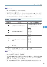
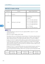
• Selector 5: Escape from phase C
This selector determines whether or not the machine will escape from phase C when it detects an RTC
(Return to Control) in non-ECM mode or an RCP (Return to Control Partial page) in ECM mode.
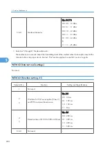
• Selectors 6 through 8: Extension of incoming calling signal (CI) frequency band specified by selectors
1 through 4 on WSW14
At the start of reception, if the machine detects the frequency of a CI signal specified by selectors 1
through 4 on WSW14, it starts the ringer sounding. However, the machine may fail to detect the CI
signal normally due to noise superimposed at the time of reception. To prevent it, use selectors 6
through 8 on WSW36.
If the machine detects higher frequencies than the setting made here, it regards them as noise and
interprets the detecting state as being normal, allowing the ringer to keep sounding according to the
preset number of ringers (until it starts automatic reception of FAX data in the FAX mode or enters the
TAD mode in the TEL mode).
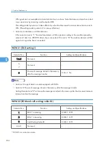
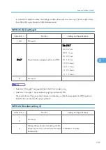
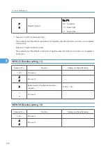
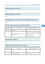
WSW37 (Function setting 15)
Selector No.
Function
Setting and Specifications
1
Printout of the stored image data of an
unsent document onto an error report
0: No 1: Yes
2
Erasure of the stored image data of an
unsent document at the time of the
subsequent inmemory message
transmission
0: No 1: Yes
3 to 8
Not used.
-
5. Service Maintenance
194
5
Summary of Contents for HL-F1
Page 1: ...Model HL F1 Machine Code H558 Field Service Manual 14 May 2010...
Page 2: ......
Page 13: ...1 Product Information Specifications See Appendices for the Specifications 11 1...
Page 15: ...Rear View 12 USB Interface Connector 13 Back Cover 14 AC Power Connector Overview 13 1...
Page 18: ...Components The equipment consists of the following major components 1 Product Information 16 1...
Page 22: ...2 Installation 20 2...
Page 23: ...3 Preventive Maintenance PM Tables There are no PM parts for this machine 21 3...
Page 24: ...3 Preventive Maintenance 22 3...
Page 33: ...Disassembly Flowchart Before You Do 31 4...
Page 44: ...5 Remove the actuator R A from the panel unit B 4 Replacement and Adjustment 42 4...
Page 45: ...6 Release the four hooks to remove the panel rear cover A x 3 B M3x8 Common Parts 43 4...
Page 48: ...11 Remove the rubber key A 4 Replacement and Adjustment 46 4...
Page 60: ...22 Remove the CIS A 23 Disconnect the CIS harness A 4 Replacement and Adjustment 58 4...
Page 61: ...24 Remove the two CIS springs A 25 Remove the LF roller gear A Common Parts 59 4...
Page 63: ...28 Remove the scanning motor F sub ASSY A x 1 M3x6 Common Parts 61 4...
Page 107: ...2 Remove the main frame R A x 3 B M4x12 Main Body 105 4...
Page 110: ...FG harness ASSY 1 Main PCB 2 FG harness ASSY 3 Laser unit 4 Replacement and Adjustment 108 4...
Page 111: ...Regist sensor PCB ASSY 1 PS PCB unit 2 Regist sensor PCB ASSY 3 Chute Harness Routing 109 4...
Page 112: ...Fan Motor 60 Unit 1 Fan motor 60 unit 2 Main PCB 4 Replacement and Adjustment 110 4...
Page 120: ...CIS 1 Main PCB 2 CIS 4 Replacement and Adjustment 118 4...
Page 155: ...10 Click Next Firmware Installation 153 5...
Page 156: ...11 To proceed click Yes 5 Service Maintenance 154 5...
Page 218: ...Image Defects 6 Troubleshooting 216 6...
Page 255: ...Model HL F1 Machine Code H558 Appendices 14 May 2010...
Page 256: ......
Page 258: ...2...


