


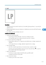
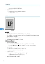


I-1 Light
User Check
1. Check the printer's environment. Conditions such as humidity, high temperatures, etc. may cause this
situation to occur.
2. If the whole page is light, toner save mode may be on. Disable toner save mode within Printer Properties
tab of the driver.
3. Try installing a new toner cartridge or drum unit.
Possible cause and Remedy
1. Toner sensor failure (printer side)
• Can printing be started with the drum unit and toner cartridge removed?
Yes: Check if the toner sensor is dirty and check the toner sensor connection.
2. Toner sensor failure (toner cartridge side)
• Is the problem solved when 4 or 5 pages are printed after the toner cartridge is replaced with
a full one?
Yes: The wiper of the toner cartridge is defective. Replace the toner cartridge.
3. Drum connection failure
• Are all the contacts between the drum unit and printer body connected correctly?
No: Clean contact electrodes both on the drum unit and in the printer body. (
(1), (4), (5),
(6) in p.240 "Location of Grounding Contacts")
4. HVPS / Main PCB failure
• Is the harness connection between the HVPS and the main PCB correct?
Yes: Replace the HVPS or the main PCB.
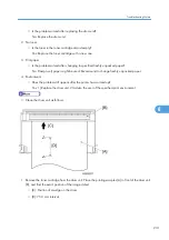
5. Dirt on the scanner window
• Is there any dirt on the scanner window?
Troubleshooting Guide
217
6
Summary of Contents for HL-F1
Page 1: ...Model HL F1 Machine Code H558 Field Service Manual 14 May 2010...
Page 2: ......
Page 13: ...1 Product Information Specifications See Appendices for the Specifications 11 1...
Page 15: ...Rear View 12 USB Interface Connector 13 Back Cover 14 AC Power Connector Overview 13 1...
Page 18: ...Components The equipment consists of the following major components 1 Product Information 16 1...
Page 22: ...2 Installation 20 2...
Page 23: ...3 Preventive Maintenance PM Tables There are no PM parts for this machine 21 3...
Page 24: ...3 Preventive Maintenance 22 3...
Page 33: ...Disassembly Flowchart Before You Do 31 4...
Page 44: ...5 Remove the actuator R A from the panel unit B 4 Replacement and Adjustment 42 4...
Page 45: ...6 Release the four hooks to remove the panel rear cover A x 3 B M3x8 Common Parts 43 4...
Page 48: ...11 Remove the rubber key A 4 Replacement and Adjustment 46 4...
Page 60: ...22 Remove the CIS A 23 Disconnect the CIS harness A 4 Replacement and Adjustment 58 4...
Page 61: ...24 Remove the two CIS springs A 25 Remove the LF roller gear A Common Parts 59 4...
Page 63: ...28 Remove the scanning motor F sub ASSY A x 1 M3x6 Common Parts 61 4...
Page 107: ...2 Remove the main frame R A x 3 B M4x12 Main Body 105 4...
Page 110: ...FG harness ASSY 1 Main PCB 2 FG harness ASSY 3 Laser unit 4 Replacement and Adjustment 108 4...
Page 111: ...Regist sensor PCB ASSY 1 PS PCB unit 2 Regist sensor PCB ASSY 3 Chute Harness Routing 109 4...
Page 112: ...Fan Motor 60 Unit 1 Fan motor 60 unit 2 Main PCB 4 Replacement and Adjustment 110 4...
Page 120: ...CIS 1 Main PCB 2 CIS 4 Replacement and Adjustment 118 4...
Page 155: ...10 Click Next Firmware Installation 153 5...
Page 156: ...11 To proceed click Yes 5 Service Maintenance 154 5...
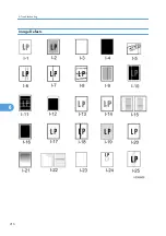
Page 218: ...Image Defects 6 Troubleshooting 216 6...
Page 255: ...Model HL F1 Machine Code H558 Appendices 14 May 2010...
Page 256: ......
Page 258: ...2...


