


F/R Solenoid ASSY...................................................................................................................................101
Main Frame L.............................................................................................................................................103
Main Frame R............................................................................................................................................104
Laser Unit....................................................................................................................................................106
FG harness ASSY 1/ FG harness ASSY 2/ FG harness ASSY 5.........................................................107
FG harness ASSY......................................................................................................................................108
Regist sensor PCB ASSY............................................................................................................................109
Fan Motor 60 Unit.....................................................................................................................................110
Toner LED PCB ASSY/ Fan 40................................................................................................................111
Toner Sensor PCB ASSY...........................................................................................................................112
P/R Solenoid ASSY/ F/R Solenoid ASSY..............................................................................................113
New Toner Sensor Harness Assy/ Cover Sensor..................................................................................114
Panel Unit...................................................................................................................................................115
Hook PCB...................................................................................................................................................116
Scanning Motor F Sub ASSY...................................................................................................................117
CIS..............................................................................................................................................................118
NCU PCB...................................................................................................................................................119
Requirement Adjustment after Parts Replacement.......................................................................................120
If You Replace the Main PCB...................................................................................................................120
If You Replace the CIS..............................................................................................................................123
If You Replace the Laser Unit....................................................................................................................123
Entry into the Maintenance Mode................................................................................................................125
List of Maintenance-Mode Functions...........................................................................................................126
User-Access to The Maintenance Mode.....................................................................................................128
Detailed Description of Maintenance-Mode Functions..............................................................................129
EEPROM Parameter Initialization (Function code 01/91)....................................................................129
Printout of Scanning Compensation Data (Function code 05)..............................................................130
ADF Performance Test (Function code 08).............................................................................................131
Test Pattern (Function code 09)................................................................................................................131
Firmware Switch Setting (Function code 10)..........................................................................................132
Printout of Firmware Switch Data (Function code 11)............................................................................136
7
Summary of Contents for HL-F1
Page 1: ...Model HL F1 Machine Code H558 Field Service Manual 14 May 2010...
Page 2: ......
Page 13: ...1 Product Information Specifications See Appendices for the Specifications 11 1...
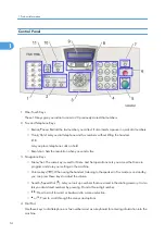
Page 15: ...Rear View 12 USB Interface Connector 13 Back Cover 14 AC Power Connector Overview 13 1...
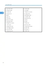
Page 18: ...Components The equipment consists of the following major components 1 Product Information 16 1...
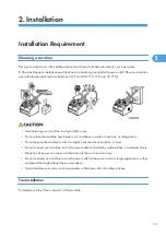
Page 22: ...2 Installation 20 2...
Page 23: ...3 Preventive Maintenance PM Tables There are no PM parts for this machine 21 3...
Page 24: ...3 Preventive Maintenance 22 3...
Page 33: ...Disassembly Flowchart Before You Do 31 4...
Page 44: ...5 Remove the actuator R A from the panel unit B 4 Replacement and Adjustment 42 4...
Page 45: ...6 Release the four hooks to remove the panel rear cover A x 3 B M3x8 Common Parts 43 4...
Page 48: ...11 Remove the rubber key A 4 Replacement and Adjustment 46 4...
Page 60: ...22 Remove the CIS A 23 Disconnect the CIS harness A 4 Replacement and Adjustment 58 4...
Page 61: ...24 Remove the two CIS springs A 25 Remove the LF roller gear A Common Parts 59 4...
Page 63: ...28 Remove the scanning motor F sub ASSY A x 1 M3x6 Common Parts 61 4...
Page 107: ...2 Remove the main frame R A x 3 B M4x12 Main Body 105 4...
Page 110: ...FG harness ASSY 1 Main PCB 2 FG harness ASSY 3 Laser unit 4 Replacement and Adjustment 108 4...
Page 111: ...Regist sensor PCB ASSY 1 PS PCB unit 2 Regist sensor PCB ASSY 3 Chute Harness Routing 109 4...
Page 112: ...Fan Motor 60 Unit 1 Fan motor 60 unit 2 Main PCB 4 Replacement and Adjustment 110 4...
Page 120: ...CIS 1 Main PCB 2 CIS 4 Replacement and Adjustment 118 4...
Page 155: ...10 Click Next Firmware Installation 153 5...
Page 156: ...11 To proceed click Yes 5 Service Maintenance 154 5...
Page 218: ...Image Defects 6 Troubleshooting 216 6...
Page 255: ...Model HL F1 Machine Code H558 Appendices 14 May 2010...
Page 256: ......
Page 258: ...2...


