Troubleshooting Guide
Introduction
This section gives the service personnel some of the troubleshooting procedures to be followed if an error
or malfunction occurs with the facsimile equipment. It is impossible to anticipate all of the possible problems
which may occur in future and determine the troubleshooting procedures, so this section covers some
sample problems. However, those samples will help service personnel pinpoint and repair other defective
elements if he/she analyzes and examines them well.
Precautions
Be sure to observe the following to prevent the secondary troubles from happening:
1. Always unplug the AC power cord from the outlet when removing the covers and PCBs, adjusting the
mechanisms, or conducting continuity testing with a circuit tester.
2. When disconnecting the connectors, do not pull the lead wires but hold the connector housings.
3. Before handling the PCBs, touch a metal portion of the machine to discharge static electricity charged
in your body.
When repairing the PCBs, handle them with extra care.
After repairing the defective section, be sure to check again if the repaired section works correctly. Also
record the troubleshooting procedure so that it would be of use for future trouble occurrence.
Checking Prior to Troubleshooting
Prior to proceeding to the troubleshooting procedures given in Section 9.2.4, make the following initial
checks:
Environmental conditions
Check that:
1. The machine is placed on a flat, firm surface.
2. The machine is used in a clean environment at or near normal room temperature (10°C to 35°C)
with normal relative humidity (20 to 80%).
3. The machine is not exposed to direct sunlight or harmful gases.
6. Troubleshooting
204
6
Summary of Contents for HL-F1
Page 1: ...Model HL F1 Machine Code H558 Field Service Manual 14 May 2010...
Page 2: ......
Page 13: ...1 Product Information Specifications See Appendices for the Specifications 11 1...
Page 15: ...Rear View 12 USB Interface Connector 13 Back Cover 14 AC Power Connector Overview 13 1...
Page 18: ...Components The equipment consists of the following major components 1 Product Information 16 1...
Page 22: ...2 Installation 20 2...
Page 23: ...3 Preventive Maintenance PM Tables There are no PM parts for this machine 21 3...
Page 24: ...3 Preventive Maintenance 22 3...
Page 33: ...Disassembly Flowchart Before You Do 31 4...
Page 44: ...5 Remove the actuator R A from the panel unit B 4 Replacement and Adjustment 42 4...
Page 45: ...6 Release the four hooks to remove the panel rear cover A x 3 B M3x8 Common Parts 43 4...
Page 48: ...11 Remove the rubber key A 4 Replacement and Adjustment 46 4...
Page 60: ...22 Remove the CIS A 23 Disconnect the CIS harness A 4 Replacement and Adjustment 58 4...
Page 61: ...24 Remove the two CIS springs A 25 Remove the LF roller gear A Common Parts 59 4...
Page 63: ...28 Remove the scanning motor F sub ASSY A x 1 M3x6 Common Parts 61 4...
Page 107: ...2 Remove the main frame R A x 3 B M4x12 Main Body 105 4...
Page 110: ...FG harness ASSY 1 Main PCB 2 FG harness ASSY 3 Laser unit 4 Replacement and Adjustment 108 4...
Page 111: ...Regist sensor PCB ASSY 1 PS PCB unit 2 Regist sensor PCB ASSY 3 Chute Harness Routing 109 4...
Page 112: ...Fan Motor 60 Unit 1 Fan motor 60 unit 2 Main PCB 4 Replacement and Adjustment 110 4...
Page 120: ...CIS 1 Main PCB 2 CIS 4 Replacement and Adjustment 118 4...
Page 155: ...10 Click Next Firmware Installation 153 5...
Page 156: ...11 To proceed click Yes 5 Service Maintenance 154 5...
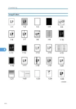
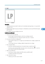
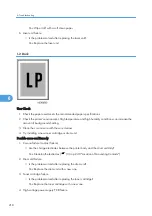
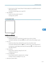
Page 218: ...Image Defects 6 Troubleshooting 216 6...
Page 255: ...Model HL F1 Machine Code H558 Appendices 14 May 2010...
Page 256: ......
Page 258: ...2...


