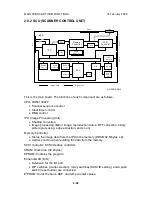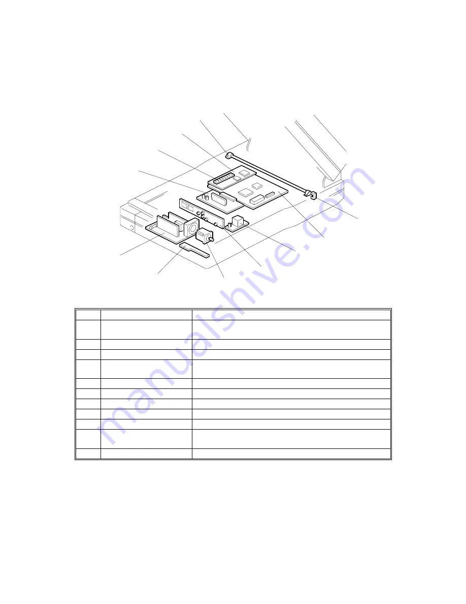
ELECTRICAL COMPONENT LAYOUT
16 February 2000
1-8
1.4 ELECTRICAL COMPONENT LAYOUT
1.4.1 SCANNER
No.
Name
Function
1
Home position sensor
Detects whether the first scanner is at the home
position.
2
SCU
Controls the overall scanner function.
3
Lamp Stabilizer
Provides ac power to the exposure lamp.
4
SBU
Contains the CCD, and outputs a video signal to the
SCU.
5
Scanner Motor
Drives the scanners.
6
SOP
This contains the scanner indicator lamps.
7
PSU
Provides dc voltages to the system.
8
IOB
Controls the mechanical parts of the scanner.
9
SIMM
32MB RAM
10
ERCU
Outputs a video signal of the reverse side of the original
to the SCU.
11
Exposure lamp
Illuminates the original for exposure.
G413V504.WMF
6
7
5
4
3
2
1
8
9
10
11


