Scanner Unit
SM 4-37
M052/M053/M054
R
e
p
la
cem
e
n
t
and
Adjus
tm
e
nt
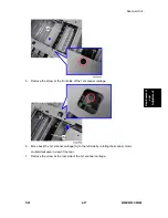
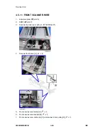
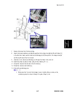
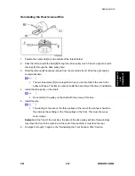
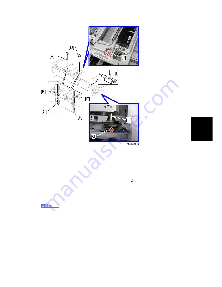
7. Remove the tape from the drive pulley.
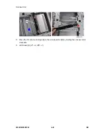
8. Insert a scanner-positioning pin [A] through the 2nd carriage hole [B] and the left holes [C]
in the front rail. Insert another scanner positioning pin [D] through the 1st carriage hole [E]
and the right holes in the front rail [F].
9. Insert two more scanner positioning pins through the holes in the rear rail.
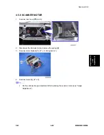
10. Install the white clip [G] and drive pulley to the shaft [H] (
x 1).
11. Screw the scanner wire bracket to the front rail [I].
12. Screw the scanner wire holder [J].
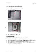
13. Pull out the positioning pins.
Make sure the 1st and 2nd carriages move smoothly after you remove the
positioning pins. Do steps 8 through 13 again if they do not.
Summary of Contents for M052
Page 1: ...M052 M053 M054 SERVICE MANUAL ...
Page 15: ......
Page 20: ...PRODUCT INFORMATION REVISION HISTORY Page Date Added Updated New None ...
Page 21: ......
Page 31: ......
Page 76: ......
Page 77: ...PREVENTIVE MAINTENANCE REVISION HISTORY Page Date Added Updated New None ...
Page 78: ......
Page 82: ......
Page 210: ...1 Bin Tray Unit M052 M053 M054 4 128 SM 10 Remove two screws A ...
Page 214: ......
Page 216: ......
Page 426: ......
Page 466: ......
Page 467: ...ENERGY SAVING REVISION HISTORY Page Date Added Updated New None ...
Page 468: ......
Page 474: ...M052 M053 M054 SERVICE MANUAL APPENDICES ...
Page 475: ......
Page 477: ......
Page 479: ......
Page 495: ......
Page 496: ...APPENDIX PREVENTIVE MAINTENANCE TABLES REVISION HISTORY Page Date Added Updated New None ...
Page 497: ......
Page 501: ...M381 FAX OPTION TYPE SP5200 REVISION HISTORY Page Date Added Updated New None ...
Page 502: ......
Page 506: ......
Page 649: ......
Page 651: ......
Page 653: ......

